一、目的:
实现多功能数字钟,具备下列功能:
1、数字钟:能计时,实现小时、分钟、秒的显示;
2、数字跑表:精度至0.01秒 比如显示12.97秒;
3、闹钟: 可以设定闹钟,用试验箱上的蜂鸣器作为闹铃;
4、调时:可以对时间进行设定;
5、日期设定:能设定日期并显示当前日期;
6、除调时状态,其他状态均不应影响系统计时。
二、设计方案与设计思路:
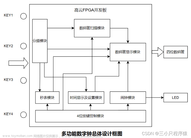
整体程序通过例化10个模块后整合形成多功能数字时钟功能,各模块名称以及各模块的作用分别为:
1、总控制模块:用于控制调整时分秒、年月日以及闹钟的模式选择,以及控制三个add按键调整的对象。
2、分频器模块:用于分频得到1Hz计时时钟。
3、时分秒调整模块:处于计时器时分秒调整设置状态时,对应控制模块的三个add按键可以实现对计时器的时分秒数值的设置,并且有按键可以实现对时分秒模块进行设置数值的载入。
4、时分秒变量处理(计时)模块:用于计时,根据分频后的时钟每隔一秒使秒变量加一,满六十向分变量进一,以此类推实现分钟以及小时的进位。
5、年月日调整模块:处于日期年月日调整设置状态时,对应控制模块的三个add按键可以实现对年月日数值的设置,并且有按键可以实现对年月日变量处理模块进行设置数值的载入。
6、年月日变量处理(计日期)模块:用于计日期,根据时分秒变量处理模块的小时值进位进行自加,小时满二十四向日变量进一,以此类推实现日以及年月的进位。
7、闹钟设置及使能模块:用于设置闹钟的时分秒数值,处于闹钟设置状态时,对应控制模块的三个add按键实现对闹钟的时分秒数值的设置,并带有可关闭开启闹钟的开关。
8、数字跑表模块:精度至0.01秒,其中包含了100Hz时钟分频模块,且可通过按键进行清零操作。
9、数码管显示控制模块:可以选择性地控制数码管显示的三个不同模式的内容。
10、可视化数码管显示模块:使用六个带译码器的静态数码管实现小时、分钟、秒或日期年、月、日或闹钟时、分、秒的显示以及数字跑表精度至0.01秒的跑秒显示。以上模块例化后可得RTL原理图如下:
三、各模块代码及仿真结果:
//总控制模块
module kongzhi(
input add2,
input add1,
input add0,
input k5,
input k6,
input k7,//控制三个add按键调整的对象
output reg sec_add,
output reg min_add,
output reg hour_add,
output reg day_add,
output reg mon_add,
output reg year_add,
output reg sec_beemp_add,
output reg min_beemp_add,
output reg hour_beemp_add
);
always @(*)
begin
case ({k5,k6,k7})
3:{year_add,mon_add,day_add}={add2,add1,add0};//选择的是调日期模式,add三个按键可增加年月日
4:{hour_beemp_add,min_beemp_add,sec_beemp_add}={add2,add1,add0};//选择的是调闹钟模式,add三个按键可增加闹钟值的时分秒
default:{hour_add,min_add,sec_add}={add2,add1,add0};//选择的是调时模式,add三个按键可增加计时器的时分秒
endcase
end
endmodule

上图为总控制模块不分频的仿真结果: 使K5 K6 K7分别为0 0 1,选择输出调时数值的结果,即:{hour_add,min_add,sec_add}={add2,add1,add0};可见输入随机信号给三个add时,各add对应的输出数组赋值结果是相匹配的。
//分频器(1Hz)
module fre_div(
input clk_in,
output reg clk,//输出的分频后的时钟
output reg clk_disp
);
parameter N=25000000;
integer cnt;
always @(posedge clk_in)
begin //分频出1Hz时钟
if(cnt == N-1)
begin
clk = ~clk; //分频后的时钟取反
clk_disp=clk;
cnt = 0;
end
else
begin //时钟更新
cnt = cnt + 1;
end
end
endmodule

上图为分频器6分频结果。

上图为50M分频结果,由于仿真时钟波形不够显示50000000次时钟波形,所以分频结果未显示出。
//计数器时分秒变量处理模块
module sfm(
input clk,
input load1, //计数器开始工作标志(1时输出有效)
input [7:0] sec_in,
input [7:0] min_in,
input [7:0] hour_in,
output reg[7:0] sec_out,
output reg[7:0] min_out,
output reg[7:0] hour_out,
output reg clk_day //满24小时后加一天的变量存储
);
reg clk_min,clk_hour;//分钟和小时的进位标志位
//输出秒的值
always@(posedge load1 or posedge clk)
begin
if(load1)
begin
sec_out=sec_in;//开始输出
end
else if(sec_out==8'd59)
begin
sec_out=0;
clk_min=1;//分钟进位标志位置1
end
else
begin
sec_out=sec_out+1;//秒自加1
clk_min=0;
end
end
//min_out
always@(posedge load1 or posedge clk_min)
begin
if(load1)
begin
min_out=min_in;//开始输出
end
else if(min_out==8'd59)
begin
min_out=0;
clk_hour=1;
end
else
begin
min_out=min_out+1;
clk_hour=0;
end
end
//hour_out
always@(posedge load1 or posedge clk_hour)
begin
if(load1)
begin
hour_out=hour_in;//开始输出
end
else if(hour_out==8'd23)
begin
hour_out=0;
clk_day=1;
end
else
begin
hour_out=hour_out+1;
clk_day=0;
end
end
endmodule

上图为计数器时分秒变量处理模块计时状态下6分频仿真的结果。
//计数器时分秒设置模块
module sfmsz(
input sec_add,
input min_add,
input hour_add,//计数器时分秒增加按键
output reg[7:0] sec_out,
output reg[7:0] min_out,
output reg[7:0] hour_out//计数器时分秒设置后的输出
);
initial
begin
sec_out='d0;
min_out='d0;
hour_out='d0;
end
//设置秒
always@(posedge sec_add)//为1时秒的输出+1
begin
begin
if(sec_out=='d59)
begin
sec_out=0;
end
else
begin
sec_out=sec_out+1;
end
end
end
//设置分
always@(posedge min_add)
begin
begin
if(min_out=='d59)
begin
min_out=0;
end
else
begin
min_out=min_out+1;
end
end
end
//设置小时
always@(posedge hour_add)
begin
begin
if(hour_out=='d23)
begin
hour_out=0;
end
else
begin
hour_out=hour_out+1;
end
end
end
endmodule

上图为不分频情况下仿真设置小时变量时的结果(分秒变量在相应add按键按下时波形与小时相同,原理一致)。
//年月日变量处理模块
module nyr(
input clk_day,
input load2,//为1时开始输出年月日
input [7:0] day_in,
input [7:0] mon_in,
input [7:0] year_in,
output reg[7:0] day_out,
output reg[7:0] mon_out,
output reg[7:0] year_out
);
reg clk_mon,clk_year;//满一月或者满一年的进位标志位
//输出日
always@(posedge load2 or posedge clk_day)
begin
if(load2)
begin
day_out=day_in;//开始输出
end
else if(day_out==8'd30)
begin
day_out=0;
clk_mon=1;
end
else
begin
day_out=day_out+1;
clk_mon=0;
end
end
//输出月
always@(posedge load2 or posedge
clk_mon)
begin
if(load2)
begin
mon_out=mon_in;//开始输出
end
else if(mon_out==8'd12)
begin
mon_out=0;
clk_year=1;
end
else
begin
mon_out=mon_out+1;
clk_year=0;
end
end
//输出年
always@(posedge load2 or posedge
clk_year)
begin
if(load2)
begin
year_out=year_in;//开始输出
end
else if(year_out==8'd22)
begin
year_out=0;
end
else
begin
year_out=year_out+1;
end
end
endmodule

上图为年月日变量处理模块不分频时的仿真结果。
//年月日设置变量模块
module nyrsz(
input day_add,
input mon_add,
input year_add,
output reg[7:0] day_out,
output reg[7:0] mon_out,
output reg[7:0] year_out
);
initial
begin
day_out='d0;
mon_out='d0;
year_out='d0;
end
//设置日
always@(posedge day_add)//为1时日的输出+1
begin
begin
if(day_out=='d30)
begin
day_out=0;
end
else
begin
day_out=day_out+1;
end
end
end
//设置月
always@(posedge mon_add)
begin
begin
if(mon_out=='d12)
begin
mon_out=0;
end
else
begin
mon_out=mon_out+1;
end
end
end
//设置年
always@(posedge year_add)
begin
begin
if(year_out=='d22)
begin
year_out=0;
end
else
begin
year_out=year_out+1;
end
end
end
endmodule

上图为年月日变量设置模块不分频时的仿真结果。
//闹钟时分秒设置模块,到达设定值后蜂鸣器响
module sfm_beemp(
input k3,
input [7:0] sec_in,
input [7:0] min_in,
input [7:0] hour_in,//检测时分秒的输入值
input sec_add,
input min_add,
input hour_add,//设置闹钟时分秒的增加按键
output reg[7:0] sec_out,
output reg[7:0] min_out,
output reg[7:0] hour_out,//设置的时分秒的闹钟值
output reg beemp//蜂鸣器输出
);
initial
begin//先设置闹钟值为000
sec_out='d0;
min_out='d0;
hour_out='d0;
end
always@( hour_in or min_in or sec_in or k3 )
begin
if (~k3)//手动控制闹钟响
beemp=1;
else
begin
if({hour_in,min_in,sec_in}=={hour_out,min_out,sec_out})//检测到的时分秒对于设置好的闹钟值时分秒,闹钟响
beemp=0;
else
beemp=beemp;
end
end
//设置闹钟值的秒
always@(posedge sec_add)//秒按键使能
begin
begin
if(sec_out=='d59)
begin
sec_out=0;
end
else
begin
sec_out=sec_out+1;
end
end
end
//设置闹钟值的分
always@(posedge min_add)
begin
begin
if(min_out=='d59)
begin
min_out=0;
end
else
begin
min_out=min_out+1;
end
end
end
//设置闹钟值的小时
always@(posedge hour_add)
begin
begin
if(hour_out=='d23)
begin
hour_out=0;
end
else
begin
hour_out=hour_out+1;
end
end
end
endmodule

上图为闹钟时分秒值设置模块设置闹钟为0点0分0秒时,不使能、不分频的仿真结果。(三个add刚开始便满足0时0分0秒条件,此时beemp=0,闹钟不响)

上图为闹钟时分秒值设置模块设置闹钟为0点0分0秒时,使能、不分频的仿真结果。(三个add刚开始便满足0时0分0秒条件,此时beemp=1,闹钟响)
//数码管显示内容的选择控制模块
module kongzhi_disp(
input k5,
input k6,
input k7,//控制数码管显示年月日还是计时器时分秒还是闹钟值时分秒
input [7:0] hour,//时分秒显示的值
input [7:0] min,
input [7:0] sec,
input [7:0] hour_set,//时分秒设置的值
input [7:0] min_set,
input [7:0] sec_set,
input [7:0] year,//年月日显示的值
input [7:0] mon,
input [7:0] day,
input [7:0] year_set,//年月日设置的值
input [7:0] mon_set,
input [7:0] day_set,
input [7:0] hour_beemp,//闹钟设置的值
input [7:0] min_beemp,
input [7:0] sec_beemp,
input [7:0] jsg,
input [7:0] jsd,
output reg[7:0] count2,
output reg[7:0] count1,
output reg[7:0] count0
);
always @(*)
case({k5,k6,k7})//不同的值显示内容不一样
0:{count2,count1,count0}={hour,min,sec};
1:{count2,count1,count0}={hour_set,min_set,sec_set};
2:{count2,count1,count0}={year,mon,day};
3:{count2,count1,count0}={year_set,mon_set,day_set};
4:{count2,count1,count0}={hour_beemp,min_beemp,sec_beemp};
6:{count1,count0}={jsg,jsd};//显示跑表计数高低位
default:{count2,count1,count0}={hour,min,sec};
endcase
endmodule

上图为数码管显示内容的选择控制模块不分频的仿真结果: 使K5 K6 K7分别为0 1 0,选择输出年月日,即:{count2,count1,count0}={year,mon,day};可见输出数组赋值结果是相匹配的。
//数字秒表及其单独的分频器模块
module mb(clk_in,count3,count4,load3);
input clk_in,load3;
output reg [6:0]count3;
output reg [6:0]count4;
reg fp;
reg [24:0]TIM;
reg jw;
always @(posedge clk_in)//数字跑表单独分频
begin
if(TIM==500000)
begin
TIM=0;
fp=~fp;
end
else
begin
TIM=TIM+1;
fp=fp;
end
end
always @(posedge fp or posedge load3)
begin
if(load3)//为1时数字跑表值为0
begin
count3=0;
end
else if(count3==8'd59)
begin
count3=0;
jw=1;
end
else
begin
count3=count3+1;
jw=0;
end
end
always @(posedge jw or posedge load3)
begin
if(load3)//为1时数字跑表值为0
begin
count4=0;
end
else if(count4==8'd59)
begin
count4=0;
end
else
begin
count4=count4+1;
end
end
endmodule

上图为数字跑表级其分频模块在6分频情况下的仿真结果。(100Hz分频仿真时钟波形不够显示500000次时钟波形无法显示,故采用6分频实现)
//数码管显示模块
module disp(
input [7:0] count,//存放显示字符真值
output reg[3:0] smgL,
output reg[3:0] smgH
);
always@( count )
begin
case( count%10 )//显示个位
4'h0 : smgL = 4'h0 ;
4'h1 : smgL = 4'h1 ;
4'h2 : smgL = 4'h2 ;
4'h3 : smgL = 4'h3 ;
4'h4 : smgL = 4'h4 ;
4'h5 : smgL = 4'h5 ;
4'h6 : smgL = 4'h6 ;
4'h7 : smgL = 4'h7 ;
4'h8 : smgL = 4'h8 ;
4'h9 : smgL = 4'h9 ;
default:smgL = 4'h0 ;
endcase
case( count/10)//显示十位
4'h0 : smgH = 4'h0 ;
4'h1 : smgH = 4'h1 ;
4'h2 : smgH = 4'h2 ;
4'h3 : smgH = 4'h3 ;
4'h4 : smgH = 4'h4 ;
4'h5 : smgH = 4'h5 ;
4'h6 : smgH = 4'h6 ;
4'h7 : smgH = 4'h7 ;
4'h8 : smgH = 4'h8 ;
4'h9 : smgH = 4'h9 ;
default:smgL = 4'h0 ;
endcase
end
endmodule
//数字跑表单独显示
module dispczw(count,smg1,smg2);
input [6:0] count;
output reg[7:0] smg1,smg2;
always@( count )
begin
case( count%10 )
4'h0 : smg1 = 8'hc0 ;
4'h1 : smg1 = 8'hf9 ;
4'h2 : smg1 = 8'ha4 ;
4'h3 : smg1 = 8'hb0 ;
4'h4 : smg1 = 8'h99 ;
4'h5 : smg1 = 8'h92 ;
4'h6 : smg1 = 8'h82 ;
4'h7 : smg1 = 8'hf8 ;
4'h8 : smg1 = 8'h80 ;
4'h9 : smg1 = 8'h90 ;
endcase
case( count/10)
4'h0 : smg2 = 8'h40 ;
4'h1 : smg2 = 8'h79 ;
4'h2 : smg2 = 8'h24 ;
4'h3 : smg2 = 8'h30 ;
4'h4 : smg2 = 8'h19 ;
4'h5 : smg2 = 8'h12 ;
4'h6 : smg2 = 8'h02 ;
4'h7 : smg2 = 8'h78 ;
4'h8 : smg2 = 8'h00 ;
4'h9 : smg2 = 8'h10 ;
endcase
end
endmodule

上图为数码管显示模块在赋给相应随机真值情况下的仿真结果。可见数码管高低四位与所赋真值相吻合。
//最终顶层例化程序
module FPGACLOCK(clk_in,clk_disp,k5,k6,k7,add2,add1,add0,beemp,load1,load2,load3,kstart_beemp,seg0,seg1,seg2,seg3,seg4,seg5);//顶层程序
input clk_in,add2,add1,add0,kstart_beemp;//时钟输入 设置时分秒(年月日,闹钟时分秒)的选择位 手动
input k5,k6,k7;//区别时分秒、年月日、闹钟设置的模式位选段
input load1,load2,load3;//三种模式的选择触发按键
output clk_disp,beemp;//显示用的时钟和蜂鸣器
output [3:0]seg0;
output [3:0]seg1;//2位数码管1
output [3:0]seg2;
output [3:0]seg3;//2位数码管2
output [3:0]seg4;
output [3:0]seg5;//2位数码管3
//连线型变量,用于模块间连线传输相应变量数据
wire clk,sec_add,min_add,hour_add,day_add,mon_add,year_add,sec_beemp_add,min_beemp_add,hour_beeemp_add;
wire [7:0]sec_set;
wire [7:0]min_set;
wire [7:0]hour_set;
wire [7:0]day_set;
wire [7:0]mon_set;
wire [7:0]year_set;
wire [7:0]sec;
wire [7:0]min;
wire [7:0]hour;
wire [7:0]day;
wire [7:0]mon;
wire [7:0]year;
wire [7:0]hour_beemp;
wire [7:0]min_beemp;
wire [7:0]sec_beemp;
wire [7:0]count0;
wire [7:0]count1;
wire [7:0]count2;
wire [7:0]count3;
wire [7:0]count4;
fre_div u0 (clk_in,clk,clk_disp);//分频器例化,敏感参数列表输入输出一一对应,下方以此类推
sfm u1 (clk,load1,sec_set,min_set,hour_set,sec,min,hour,clk_day);
sfmsz u2 (sec_add,min_add,hour_add,sec_set,min_set,hour_set);
nyr u3 (clk_day,load2,day_set,mon_set,year_set,day,mon,year);
nyrsz u4 (day_add,mon_add,year_add,day_set,mon_set,year_set);
sfm_beemp u5 (kstart_beemp,sec,min,hour,sec_beemp_add,min_beemp_add,hour_beeemp_add,sec_beemp,min_beemp,hour_beemp,beemp);
kongzhi_disp u6 (k5,k6,k7,hour,min,sec,hour_set,min_set,sec_set,year,mon,day,year_set,mon_set,day_set,hour_beemp,min_beemp,sec_beemp,count4,count3,count2,count1,count0);
kongzhi u7 (add2,add1,add0,k5,k6,k7,sec_add,min_add,hour_add,day_add,mon_add,year_add,sec_beemp_add,min_beemp_add,hour_beeemp_add);
disp u8 (count2,seg4,seg5);
disp u9 (count1,seg2,seg3);
disp u10 (count0,seg0,seg1);
mb u11 (clk_in,count3,count4,load3);
endmodule
 上图为各模块例化结果,例化后系统总体仿真可以通过。(下图以随机信号输入,观察同一X轴坐标为例,可判断出不同赋值情况下数码管的输出状态):

四、程序下载至FPGA实验箱的实际结果:
1、管脚约束情况:

2、实物演示效果:

上图为计时器(时钟)调整以及显示模式工作情况(04时05分28-31秒)

上图为日期调整以及日期显示模式工作情况(21年12月08日)

上图为数字跑表(精确至0.01秒)模式工作情况(00.00秒-04.26秒)

上图为设置闹钟报时时间(6时19分05秒时闹铃)

上图为设置计数器(时钟)目前时间(当前时刻:6时19分00秒)

上图左(时刻:6时19分03秒)尚未达到闹钟设置时间,LED2不亮,闹钟不响。文章来源:https://www.toymoban.com/news/detail-417014.html
上图右(时刻:6时19分06秒)已经达到闹钟设置时间,LED2亮,闹钟响。文章来源地址https://www.toymoban.com/news/detail-417014.html
到了这里,关于数字系统设计(FPGA)课程设计: 多功能数字钟的文章就介绍完了。如果您还想了解更多内容,请在右上角搜索TOY模板网以前的文章或继续浏览下面的相关文章,希望大家以后多多支持TOY模板网!


