一、实验内容。
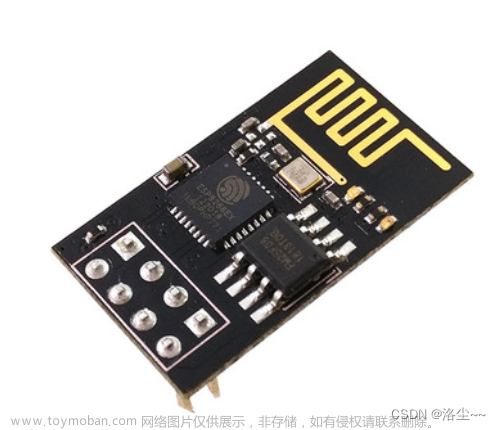
定义两个串口,分别接收两个按键输入0、1,或接收PC发送的AT指令,两个输入,通过按键切换输入到esp8266,从而完成WiFi连接、TCP服务器连接、以及数据0、1发送。
二、系统架构。

三、RTL视图

四、项目代码。
uart_tx.v串口发送模块
// uart_tx.v
`include "param.v"
module uart_tx(
	input wire 			clk	,
	input wire 			rst_n	,
	input wire 			tx_req,//发送请求
	input wire [7:0] 	tx_din,//并行数据输入

	output reg        tx_dout,//串行数据输出
	output wire       dout_vld//并转串完成标志


);
reg [12:0] cnt_bps		;//波特率计数寄存器
wire       add_cnt_bps	;//波特率计数开始
wire       end_cnt_bps  ;//波特率计数结束

reg [3:0]  cnt_bit      ;//比特计数寄存器
wire       add_cnt_bit  ;//比特计数开始
wire       end_cnt_bit  ;//比特计数结束

reg        tx_flag      ;//发送标志

reg [9:0]  tx_data      ;

//波特率计数器设计
always @(posedge clk or negedge rst_n)begin
	if(!rst_n)begin
		cnt_bps <= 13'd0;
	end
	else if(add_cnt_bps)begin
		if(end_cnt_bps)begin
			cnt_bps <= 13'd0;
		end
		else begin
			cnt_bps <= cnt_bps + 1'd1;
		end
	end
	else begin
		cnt_bps <= cnt_bps;
	end
end

assign add_cnt_bps = tx_flag;
assign end_cnt_bps = add_cnt_bps && cnt_bps == (`SYS_FRQ/`BAUD_MAX) - 1'd1;

always @(posedge clk or negedge rst_n)begin
	if(!rst_n)begin
		cnt_bit <= 4'd0;
	end
	else if(add_cnt_bit)begin
		if(end_cnt_bit)begin
			cnt_bit <= 4'd0;
		end
		else begin
			cnt_bit <= cnt_bit + 1'd1;
		end
	end
	else begin
		cnt_bit <= cnt_bit;
	end
end

assign add_cnt_bit = end_cnt_bps;
assign end_cnt_bit = add_cnt_bit && cnt_bit == 9;

//发送标志tx_flag
always @(posedge clk or negedge rst_n)begin
	if(!rst_n)begin
		tx_flag <= 1'b0;
	end
	else if(tx_req)begin
		tx_flag <= 1'b1;
	end
	else if(end_cnt_bit)begin
		tx_flag <= 1'b0;
	end
	else begin
		tx_flag <= tx_flag;
	end
end


//数据缓存,tx_data
always @(posedge clk or negedge rst_n)begin
	if(!rst_n)begin
		tx_data <= 10'b0;
	end
	else if(tx_req)begin
		tx_data <= {1'b1, tx_din, 1'b0};
	end
	else begin
		tx_data <= tx_data;
	end
end

//tx_dout数据串行输出
always @(posedge clk or negedge rst_n)begin
	if(!rst_n)begin
		tx_dout <= 1'b1;
	end
	else if(tx_flag && cnt_bps == 1)begin
		tx_dout <= tx_data[cnt_bit];
	end
	else begin
		tx_dout <= tx_dout;
	end
end

//dout_vld约束
assign dout_vld = ~tx_flag;

endmodule
uart_rx.v串口接收模块
`include "param.v"
module uart_rx(
	input wire 			clk		,
	input wire 			rst_n		,
	input wire 			rx_din	,//串行数据输入

	output wire [7:0] rx_dout	,//并行数据输出
	output reg 		   dout_vld//串转并完成标志
);

reg [12:0] cnt_bps		;//波特率计数寄存器
wire       add_cnt_bps	;//波特率计数开始
wire       end_cnt_bps	;//波特率计数结束

reg [3:0]  cnt_bit      ;//比特计数寄存器
wire       add_cnt_bit  ;//比特计数开始
wire       end_cnt_bit  ;//比特计数结束

reg 			rx_din_r0;//同步
reg 			rx_din_r1;//打拍
wire     	nedge		;//下降沿

reg      	rx_flag;//接受标志

reg [9:0] 	rx_data;//寄存数据包


//波特率计数器设计
always @(posedge clk or negedge rst_n)begin
	if(!rst_n)begin
		cnt_bps <= 13'd0;
	end
	else if(add_cnt_bps)begin
		if(end_cnt_bps)begin
			cnt_bps <= 13'd0;
		end
		else begin
			cnt_bps <= cnt_bps + 1'd1;
		end
	end
	else begin
		cnt_bps <= cnt_bps;
	end
end

assign add_cnt_bps = rx_flag;
assign end_cnt_bps = add_cnt_bps && cnt_bps == (`SYS_FRQ / `BAUD_MAX) - 1'd1;

//比特计数器设计
always @(posedge clk or negedge rst_n)begin
	if(!rst_n)begin
		cnt_bit <= 4'd0;
	end
	else if(add_cnt_bit)begin
		if(end_cnt_bit)begin
			cnt_bit <= 4'd0;
		end
		else begin
			cnt_bit <= cnt_bit + 1'd1;
		end
	end
	else begin
		cnt_bit <= cnt_bit;
	end
end

assign add_cnt_bit = end_cnt_bps;
assign end_cnt_bit = add_cnt_bit && cnt_bit == 4'd10 - 1'd1;

//起始位位置检测
always @(posedge clk or negedge rst_n)begin
	if(!rst_n)begin
		rx_din_r0 <= 1'b1;
		rx_din_r1 <= 1'b1;
	end
	else begin
		rx_din_r0 <= rx_din;
		rx_din_r1 <= rx_din_r0;
	end
end

assign nedge = ~rx_din_r0 && rx_din_r1;

//接受标志rx_flag约束
always @(posedge clk or negedge rst_n)begin
	if(!rst_n)begin
		rx_flag <= 1'b0;
	end
	else if(nedge)begin
		rx_flag <= 1'b1;
	end
	else if(end_cnt_bit)begin
		rx_flag <= 1'b0;
	end
	else begin
		rx_flag <= rx_flag;
	end

end

//缓存接受到的数据
always @(posedge clk or negedge rst_n)begin
	if(!rst_n)begin
		rx_data <= 10'b0;
	end
	else if(rx_flag && cnt_bps == (`SYS_FRQ/`BAUD_MAX) >> 1)begin
		rx_data[cnt_bit] = rx_din_r0;
	end
	else begin
		rx_data <= rx_data;
	end

end

assign rx_dout = rx_data[8:1];

//串转并完成标志dout_vld约束
always @(posedge clk or negedge rst_n)begin
	if(!rst_n)begin
		dout_vld <= 1'b0;
	end
	else if(end_cnt_bit)begin
		dout_vld <= 1'b1;
	end
	else begin
		dout_vld <= 1'b0;
	end
end

endmodule
param.v波特率常量定义
`define SYS_FRQ 50_000_000
`define BAUD_115200

`ifdef BAUD_9600
	`define BAUD_MAX 9600
`elsif BAUD_19200
	`define BAUD_MAX 19200
`elsif BAUD_38400
	`define BAUD_MAX 38400
`elsif BAUD_57600
	`define BAUD_MAX 57600
`elsif BAUD_115200
	`define BAUD_MAX 115200
`else
	`define BAUD_MAX 9600
`endif
key_debounce.v按键消抖模块
module key_debounce(
    input clk,
    input rst_n,
    input key,

    output reg temp
);

parameter DELAY = 20'd1000_000;


reg [19:0] delay_cnt;
reg key_reg;//保存上一时刻的键值
reg flag,key_value;

always @(posedge clk or negedge rst_n) begin
    if(!rst_n)begin
        delay_cnt <= 20'd0;
        key_reg   <= 1'b1;
    end
    else begin
        key_reg <= key;
        if(key_reg != key)begin
            delay_cnt <= DELAY;
        end
        else begin
            if(delay_cnt > 20'd0)begin
                delay_cnt <= delay_cnt - 1'd1;
            end
            else begin
                delay_cnt <= 20'd0;
            end
        end
    end
end

always @(posedge clk or negedge rst_n) begin
   if(!rst_n)begin
    flag <= 1'b0;
    key_value <= 1'b1;
   end
   else if(delay_cnt == 1'd1)begin
    flag      <= 1'b1;
    key_value <= key;
   end
   else begin
    flag <= 1'b0;
    key_value <= key_value;
   end
end

always @(posedge clk or negedge rst_n) begin
	if(!rst_n)begin
		temp <= 1'b0;
	end
	else begin
		if(flag&&~key_value)begin
			temp <= 1'b1;
		end
		else
			temp <= 1'b0;
	end
end
endmodule
date_send.v数据发送模块
`include "param.v"
module date_send(
	input wire 			clk	,
	input wire 			rst_n	,
	input wire	[1:0]	key,
	output reg          tx_dout//串行数据输出
);
reg 		tx_req;//发送请求
reg [7:0] 	tx_din;//并行数据输入
reg [12:0] cnt_bps		;//波特率计数寄存器
wire       add_cnt_bps	;//波特率计数开始
wire       end_cnt_bps  ;//波特率计数结束

reg [3:0]  cnt_bit      ;//比特计数寄存器
wire       add_cnt_bit  ;//比特计数开始
wire       end_cnt_bit  ;//比特计数结束

reg        tx_flag      ;//发送标志

reg [9:0]  tx_data      ;

always @(posedge clk or negedge rst_n)begin
	if(!rst_n)begin
		tx_req <= 0;
		tx_din <= 0;
	end
	else if(key[0]&&!key[1])begin
		tx_req <= 1;
		tx_din <= 8'd48;
	end
	else if(key[1]&&!key[0])begin
		tx_req <= 1;
		tx_din <= 8'd49;
	end
	else begin
		tx_req <= 0;
	end
end

//波特率计数器设计
always @(posedge clk or negedge rst_n)begin
	if(!rst_n)begin
		cnt_bps <= 13'd0;
	end
	else if(add_cnt_bps)begin
		if(end_cnt_bps)begin
			cnt_bps <= 13'd0;
		end
		else begin
			cnt_bps <= cnt_bps + 1'd1;
		end
	end
	else begin
		cnt_bps <= cnt_bps;
	end
end

assign add_cnt_bps = tx_flag;
assign end_cnt_bps = add_cnt_bps && cnt_bps == (`SYS_FRQ/`BAUD_MAX) - 1'd1;

always @(posedge clk or negedge rst_n)begin
	if(!rst_n)begin
		cnt_bit <= 4'd0;
	end
	else if(add_cnt_bit)begin
		if(end_cnt_bit)begin
			cnt_bit <= 4'd0;
		end
		else begin
			cnt_bit <= cnt_bit + 1'd1;
		end
	end
	else begin
		cnt_bit <= cnt_bit;
	end
end

assign add_cnt_bit = end_cnt_bps;
assign end_cnt_bit = add_cnt_bit && cnt_bit == 9;

//发送标志tx_flag
always @(posedge clk or negedge rst_n)begin
	if(!rst_n)begin
		tx_flag <= 1'b0;
	end
	else if(tx_req)begin
		tx_flag <= 1'b1;
	end
	else if(end_cnt_bit)begin
		tx_flag <= 1'b0;
	end
	else begin
		tx_flag <= tx_flag;
	end
end


//数据缓存,tx_data
always @(posedge clk or negedge rst_n)begin
	if(!rst_n)begin
		tx_data <= 10'b0;
	end
	else if(tx_req)begin
		tx_data <= {1'b1, tx_din, 1'b0};
	end
	else begin
		tx_data <= tx_data;
	end
end

//tx_dout数据串行输出
always @(posedge clk or negedge rst_n)begin
	if(!rst_n)begin
		tx_dout <= 1'b1;
	end
	else if(tx_flag && cnt_bps == 1)begin
		tx_dout <= tx_data[cnt_bit];
	end
	else begin
		tx_dout <= tx_dout;
	end
end

//dout_vld约束
assign dout_vld = ~tx_flag;

endmodule
uart.v顶层模块
module uart(
	input wire 	clk	,
	input wire 	rst_n	,
	input	[2:0]	key	,
	input wire 	rx_esp,
	output wire tx_esp,     //串行输出
	input wire 	rx_pc,
	output wire tx_pc     //串行输出
	);

wire [7:0] rx_byte		;
wire       rx_byte_vld	;
wire [7:0] rx_byte1		;
wire       rx_byte_vld1	;
wire [2:0] temp			;
wire	   tx_AT	 	;
wire	   tx_data	 	;

reg		en;
assign tx_esp=en==1?tx_AT:tx_data;

always @(posedge clk or negedge rst_n)begin
	if(!rst_n)begin
		en <= 0;
	end
	else if(temp[0])begin
		en <= ~en;
	end
	else begin
		en <= en;
	end
end
key_debounce(
.clk(clk),
.rst_n(rst_n),
.key(key[0]),

.temp(temp[0])
);


key_debounce(
.clk(clk),
.rst_n(rst_n),
.key(key[1]),

.temp(temp[1])
);


key_debounce(
.clk(clk),
.rst_n(rst_n),
.key(key[2]),

.temp(temp[2])
);

uart_rx u_uart_rx(
.clk		(clk),
.rst_n	(rst_n),
.rx_din	(rx_pc),//串行数据输入

.rx_dout	(rx_byte),//并行数据输出
.dout_vld(rx_byte_vld)//串转并完成标志
);


uart_rx u_uart_rx1(
.clk		(clk),
.rst_n	(rst_n),
.rx_din	(rx_esp),//串行数据输入

.rx_dout	(rx_byte1),//并行数据输出
.dout_vld(rx_byte_vld1)//串转并完成标志
);


uart_tx u_uart_tx(
.clk	(clk),
.rst_n	(rst_n),
.tx_req(rx_byte_vld),//发送请求
.tx_din(rx_byte),//并行数据输入

.tx_dout(tx_AT)//串行数据输出
//.dout_vld()//并转串完成标志


);

date_send u_date_send(
.clk	(clk),
.rst_n	(rst_n),
.key	(temp[2:1]),
.tx_dout(tx_data)//串行数据输出

);

uart_tx u_uart_tx1(
.clk	(clk),
.rst_n	(rst_n),
.tx_req(rx_byte_vld1),//发送请求
.tx_din(rx_byte1),//并行数据输入

.tx_dout(tx_pc)//串行数据输出
//.dout_vld()//并转串完成标志


);
endmodule
五、具体操作及运行结果。
1.按照管教分配连接ESP8266.
2.连接WiFi
按下key1,将串口tx端切换到PC,此时可接收来自串口调试助手的数据。
在串口调试助手中选择开发板端口,并打开串口。
输入 AT+RST 重启ESP8266模块。
输入 AT+CWMODE=1 将模块设置为Station模式。(可能会因编码原因返回乱码)
输入 AT+CWJAP=“SSID”,“PWD” 该命令为连接路由器发出的WiFi信号,SSID为此WiFi的用户名,PWD为此PWD的密码。如果返回乱码,可在路由器后台,或电脑热点设置中查看是否连接成功。
在热点设置中查看到,esp8266连接成功。
3.创建TCP服务器
打开Socket tool,并创建端口为6666的TCP服务器。
打开串口调试助手,输入并发送指令:
AT+CIPSTART=“TCP”,“172.16.103.242”,6666(此处可根据自己实际情况修改ip及端口)
4.发送数据
输入 AT+CIPMODE=1 打开透传模式。
输入 AT+CIPSEND 设置发送数据长度。(AT+CIPSEND=14(等于符号后的数字代表发送数据的长度,此处我们暂不设置数字长度))
按下key1切换输入为按键输入。
按下key2、key3分别发送0、1至TCP服务器。 文章来源:https://www.toymoban.com/news/detail-463972.html
六、总结。
本实验主要就是理解串口各个端口的作用,以及串口发送单个字符。文章来源地址https://www.toymoban.com/news/detail-463972.html
到了这里,关于FPGA——ESP8266发送0、1实验的文章就介绍完了。如果您还想了解更多内容,请在右上角搜索TOY模板网以前的文章或继续浏览下面的相关文章,希望大家以后多多支持TOY模板网!


