1 简介
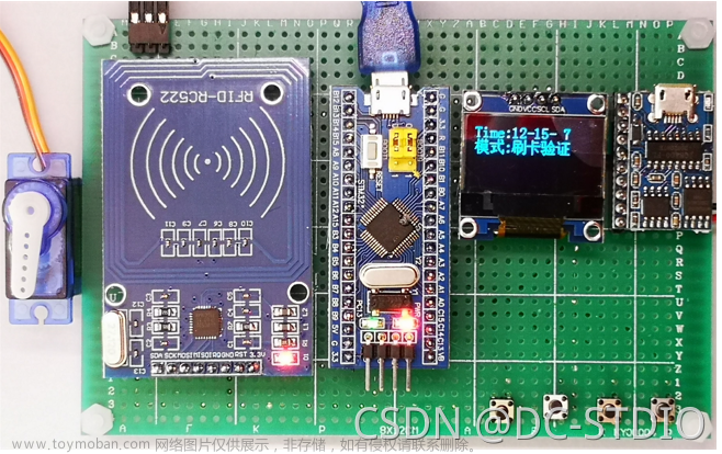
Hi,大家好,今天向大家介绍一个学长做的单片机项目
基于STM32的心率检测器的设计与实现
大家可用于 课程设计 或 毕业设计
2 主要器件
- 主控:STM32F103C8T6
- MAX30102传感器
- OLED屏幕:用于显示实时心率波形
3 实现效果
未测试时的状态:心率波形显为平稳直线,即0
将手指放上进行心率测试: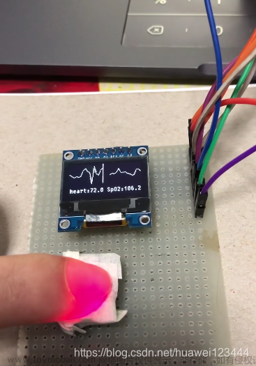
还可以把图像做成心形的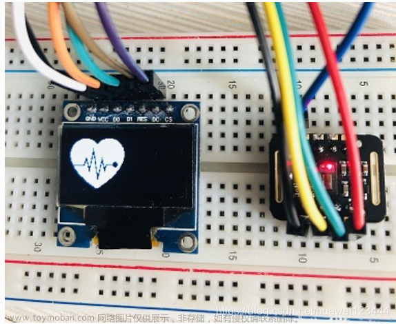
4 设计原理
4.1 MAX30102 模块
MAX30102是一个集成的脉搏血氧仪和心率监测仪生物传感器的模块。它集成了一个红光 LEO 和一个红外光 LEO 、光电检测器、光器件,以及带环境光抑制的低噪声电子电路。MAX30102采用一个 1.8V电源和一个独立的 5.0V 用于内部 LEO 的电源,应用于可穿戴设备进行心率和血氧采集检测,佩戴于手指、耳垂和手腕等处。标准的I2C兼容的通信接口可以将采集到的数值传输给Arduino、STM32 等单片机进行心率和血氧计算。此外,该芯片还可通过软件关断模块,待机电流接近为零,实现电源始终维持供电状态。
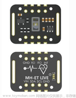

芯片内部电路图: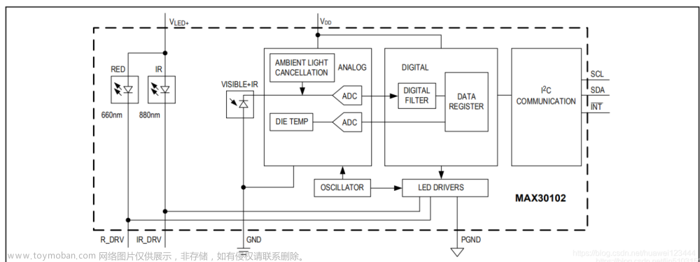
4.2 心率检测的基本原理
4.2.1 PPG光电容积法
由于人体的皮肤、骨骼、肌肉、脂肪等对于光的反射是固定值,而毛细血管和动脉、静脉由于随着脉搏容积不停变大变小,所以对光的反射值是波动值,而这个波动值正好与心率一致,所以光电容积法正是通过这个波动的频率来确定使用者的心率数据。
目前市面上绝大多数的智能手环/手表都采用这种方式监测心率,而且这种方式的技术方案已经比较成熟,所以价格也相对较低。
4.2.2 心电信号测量法
还有一种就是心电信号测量法,它通过智能穿戴设备上搭载的传感器捕捉人每次心跳时微小的电极变化,再经过算法还原出心率跳动的频率,原理和心电图类似原理。目前已经很少有智能穿戴设备采用这种方式了。文章来源:https://www.toymoban.com/news/detail-470630.html
5 部分实现代码
心率血样算法:文章来源地址https://www.toymoban.com/news/detail-470630.html
/** \file algorithm.c ******************************************************
*
* Project: MAXREFDES117#
* Filename: algorithm.cpp
* Description: This module calculates the heart rate/SpO2 level
*
*
* --------------------------------------------------------------------
*
* This code follows the following naming conventions:
*
* char              ch_pmod_value
* char (array)      s_pmod_s_string[16]
* float             f_pmod_value
* int32_t           n_pmod_value
* int32_t (array)   an_pmod_value[16]
* int16_t           w_pmod_value
* int16_t (array)   aw_pmod_value[16]
* uint16_t          uw_pmod_value
* uint16_t (array)  auw_pmod_value[16]
* uint8_t           uch_pmod_value
* uint8_t (array)   auch_pmod_buffer[16]
* uint32_t          un_pmod_value
* int32_t *         pn_pmod_value
*
* ------------------------------------------------------------------------- */
/*******************************************************************************
* Copyright (C) 2016 Maxim Integrated Products, Inc., All Rights Reserved.
*
* Permission is hereby granted, free of charge, to any person obtaining a
* copy of this software and associated documentation files (the "Software"),
* to deal in the Software without restriction, including without limitation
* the rights to use, copy, modify, merge, publish, distribute, sublicense,
* and/or sell copies of the Software, and to permit persons to whom the
* Software is furnished to do so, subject to the following conditions:
*
* The above copyright notice and this permission notice shall be included
* in all copies or substantial portions of the Software.
*
* THE SOFTWARE IS PROVIDED "AS IS", WITHOUT WARRANTY OF ANY KIND, EXPRESS
* OR IMPLIED, INCLUDING BUT NOT LIMITED TO THE WARRANTIES OF
* MERCHANTABILITY, FITNESS FOR A PARTICULAR PURPOSE AND NONINFRINGEMENT.
* IN NO EVENT SHALL MAXIM INTEGRATED BE LIABLE FOR ANY CLAIM, DAMAGES
* OR OTHER LIABILITY, WHETHER IN AN ACTION OF CONTRACT, TORT OR OTHERWISE,
* ARISING FROM, OUT OF OR IN CONNECTION WITH THE SOFTWARE OR THE USE OR
* OTHER DEALINGS IN THE SOFTWARE.
*
* Except as contained in this notice, the name of Maxim Integrated
* Products, Inc. shall not be used except as stated in the Maxim Integrated
* Products, Inc. Branding Policy.
*
* The mere transfer of this software does not imply any licenses
* of trade secrets, proprietary technology, copyrights, patents,
* trademarks, maskwork rights, or any other form of intellectual
* property whatsoever. Maxim Integrated Products, Inc. retains all
* ownership rights.
*******************************************************************************
*/
#include "algorithm.h"

const uint16_t auw_hamm[31]={ 41,    276,    512,    276,     41 }; //Hamm=  long16(512* hamming(5)');
//uch_spo2_table is computed as  -45.060*ratioAverage* ratioAverage + 30.354 *ratioAverage + 94.845 ;
const uint8_t uch_spo2_table[184]={ 95, 95, 95, 96, 96, 96, 97, 97, 97, 97, 97, 98, 98, 98, 98, 98, 99, 99, 99, 99,
                            99, 99, 99, 99, 100, 100, 100, 100, 100, 100, 100, 100, 100, 100, 100, 100, 100, 100, 100, 100,
                            100, 100, 100, 100, 99, 99, 99, 99, 99, 99, 99, 99, 98, 98, 98, 98, 98, 98, 97, 97,
                            97, 97, 96, 96, 96, 96, 95, 95, 95, 94, 94, 94, 93, 93, 93, 92, 92, 92, 91, 91,
                            90, 90, 89, 89, 89, 88, 88, 87, 87, 86, 86, 85, 85, 84, 84, 83, 82, 82, 81, 81,
                            80, 80, 79, 78, 78, 77, 76, 76, 75, 74, 74, 73, 72, 72, 71, 70, 69, 69, 68, 67,
                            66, 66, 65, 64, 63, 62, 62, 61, 60, 59, 58, 57, 56, 56, 55, 54, 53, 52, 51, 50,
                            49, 48, 47, 46, 45, 44, 43, 42, 41, 40, 39, 38, 37, 36, 35, 34, 33, 31, 30, 29,
                            28, 27, 26, 25, 23, 22, 21, 20, 19, 17, 16, 15, 14, 12, 11, 10, 9, 7, 6, 5,
                            3, 2, 1 } ;
static  int32_t an_dx[ BUFFER_SIZE-MA4_SIZE]; // delta
static  int32_t an_x[ BUFFER_SIZE]; //ir
static  int32_t an_y[ BUFFER_SIZE]; //red

void maxim_heart_rate_and_oxygen_saturation(uint32_t *pun_ir_buffer,  int16_t n_ir_buffer_length, uint32_t *pun_red_buffer, int16_t *pn_spo2, int8_t *pch_spo2_valid,
                              int16_t *pn_heart_rate, int8_t  *pch_hr_valid)
/**
* \brief        Calculate the heart rate and SpO2 level
* \par          Details
*               By detecting  peaks of PPG cycle and corresponding AC/DC of red/infra-red signal, the ratio for the SPO2 is computed.
*               Since this algorithm is aiming for Arm M0/M3. formaula for SPO2 did not achieve the accuracy due to register overflow.
*               Thus, accurate SPO2 is precalculated and save longo uch_spo2_table[] per each ratio.
*
* \param[in]    *pun_ir_buffer           - IR sensor data buffer
* \param[in]    n_ir_buffer_length      - IR sensor data buffer length
* \param[in]    *pun_red_buffer          - Red sensor data buffer
* \param[out]    *pn_spo2                - Calculated SpO2 value
* \param[out]    *pch_spo2_valid         - 1 if the calculated SpO2 value is valid
* \param[out]    *pn_heart_rate          - Calculated heart rate value
* \param[out]    *pch_hr_valid           - 1 if the calculated heart rate value is valid
*
* \retval       None
*/
{
    uint32_t un_ir_mean ,un_only_once ;
    int32_t k ,n_i_ratio_count;
    int32_t i, s, m, n_exact_ir_valley_locs_count ,n_middle_idx;
    int32_t n_th1, n_npks,n_c_min;
    int32_t an_ir_valley_locs[15] ;
    int32_t an_exact_ir_valley_locs[15] ;
    int32_t an_dx_peak_locs[15] ;
    int32_t n_peak_interval_sum;

    int32_t n_y_ac, n_x_ac;
    int32_t n_spo2_calc;
    int32_t n_y_dc_max, n_x_dc_max;
    int32_t n_y_dc_max_idx, n_x_dc_max_idx;
    int32_t an_ratio[5],n_ratio_average;
    int32_t n_nume,  n_denom ;
    // remove DC of ir signal
    un_ir_mean =0;
    for (k=0 ; k<n_ir_buffer_length ; k++ ) un_ir_mean += pun_ir_buffer[k] ;
    un_ir_mean =un_ir_mean/n_ir_buffer_length ;
    for (k=0 ; k<n_ir_buffer_length ; k++ )  an_x[k] =  pun_ir_buffer[k] - un_ir_mean ;

    // 4 pt Moving Average
    for(k=0; k< BUFFER_SIZE-MA4_SIZE; k++){
        n_denom= ( an_x[k]+an_x[k+1]+ an_x[k+2]+ an_x[k+3]);
        an_x[k]=  n_denom/(int32_t)4;
    }

    // get difference of smoothed IR signal

    for( k=0; k<BUFFER_SIZE-MA4_SIZE-1;  k++)
        an_dx[k]= (an_x[k+1]- an_x[k]);

    // 2-pt Moving Average to an_dx
    for(k=0; k< BUFFER_SIZE-MA4_SIZE-2; k++){
        an_dx[k] =  ( an_dx[k]+an_dx[k+1])/2 ;
    }

    // hamming window
    // flip wave form so that we can detect valley with peak detector
    for ( i=0 ; i<BUFFER_SIZE-HAMMING_SIZE-MA4_SIZE-2 ;i++){
        s= 0;
        for( k=i; k<i+ HAMMING_SIZE ;k++){
            s -= an_dx[k] *auw_hamm[k-i] ;
                     }
        an_dx[i]= s/ (int32_t)1146; // divide by sum of auw_hamm
    }


    n_th1=0; // threshold calculation
    for ( k=0 ; k<BUFFER_SIZE-HAMMING_SIZE ;k++){
        n_th1 += ((an_dx[k]>0)? an_dx[k] : ((int32_t)0-an_dx[k])) ;
    }
    n_th1= n_th1/ ( BUFFER_SIZE-HAMMING_SIZE);
    // peak location is acutally index for sharpest location of raw signal since we flipped the signal
    maxim_find_peaks( an_dx_peak_locs, &n_npks, an_dx, BUFFER_SIZE-HAMMING_SIZE, n_th1, 8, 5 );//peak_height, peak_distance, max_num_peaks

    n_peak_interval_sum =0;
    if (n_npks>=2){
        for (k=1; k<n_npks; k++)
            n_peak_interval_sum += (an_dx_peak_locs[k]-an_dx_peak_locs[k -1]);
        n_peak_interval_sum=n_peak_interval_sum/(n_npks-1);
        *pn_heart_rate=(int32_t)(6000/n_peak_interval_sum);// beats per minutes
        *pch_hr_valid  = 1;
    }
    else  {
        *pn_heart_rate = -999;
        *pch_hr_valid  = 0;
    }

    for ( k=0 ; k<n_npks ;k++)
        an_ir_valley_locs[k]=an_dx_peak_locs[k]+HAMMING_SIZE/2;


    // raw value : RED(=y) and IR(=X)
    // we need to assess DC and AC value of ir and red PPG.
    for (k=0 ; k<n_ir_buffer_length ; k++ )  {
        an_x[k] =  pun_ir_buffer[k] ;
        an_y[k] =  pun_red_buffer[k] ;
    }

    // find precise min near an_ir_valley_locs
    n_exact_ir_valley_locs_count =0;
    for(k=0 ; k<n_npks ;k++){
        un_only_once =1;
        m=an_ir_valley_locs[k];
        n_c_min= 16777216;//2^24;
        if (m+5 <  BUFFER_SIZE-HAMMING_SIZE  && m-5 >0){
            for(i= m-5;i<m+5; i++)
                if (an_x[i]<n_c_min){
                    if (un_only_once >0){
                       un_only_once =0;
                   }
                   n_c_min= an_x[i] ;
                   an_exact_ir_valley_locs[k]=i;
                }
            if (un_only_once ==0)
                n_exact_ir_valley_locs_count ++ ;
        }
    }
    if (n_exact_ir_valley_locs_count <2 ){
       *pn_spo2 =  -999 ; // do not use SPO2 since signal ratio is out of range
       *pch_spo2_valid  = 0;
       return;
    }
    // 4 pt MA
    for(k=0; k< BUFFER_SIZE-MA4_SIZE; k++){
        an_x[k]=( an_x[k]+an_x[k+1]+ an_x[k+2]+ an_x[k+3])/(int32_t)4;
        an_y[k]=( an_y[k]+an_y[k+1]+ an_y[k+2]+ an_y[k+3])/(int32_t)4;
    }

    //using an_exact_ir_valley_locs , find ir-red DC andir-red AC for SPO2 calibration ratio
    //finding AC/DC maximum of raw ir * red between two valley locations
    n_ratio_average =0;
    n_i_ratio_count =0;

    for(k=0; k< 5; k++) an_ratio[k]=0;
    for (k=0; k< n_exact_ir_valley_locs_count; k++){
        if (an_exact_ir_valley_locs[k] > BUFFER_SIZE ){
            *pn_spo2 =  -999 ; // do not use SPO2 since valley loc is out of range
            *pch_spo2_valid  = 0;
            return;
        }
    }
    // find max between two valley locations
    // and use ratio betwen AC compoent of Ir & Red and DC compoent of Ir & Red for SPO2

    for (k=0; k< n_exact_ir_valley_locs_count-1; k++){
        n_y_dc_max= -16777216 ;
        n_x_dc_max= - 16777216;
        if (an_exact_ir_valley_locs[k+1]-an_exact_ir_valley_locs[k] >10){
            for (i=an_exact_ir_valley_locs[k]; i< an_exact_ir_valley_locs[k+1]; i++){
                if (an_x[i]> n_x_dc_max) {n_x_dc_max =an_x[i];n_x_dc_max_idx =i; }
                if (an_y[i]> n_y_dc_max) {n_y_dc_max =an_y[i];n_y_dc_max_idx=i;}
            }
            n_y_ac= (an_y[an_exact_ir_valley_locs[k+1]] - an_y[an_exact_ir_valley_locs[k] ] )*(n_y_dc_max_idx -an_exact_ir_valley_locs[k]); //red
            n_y_ac=  an_y[an_exact_ir_valley_locs[k]] + n_y_ac/ (an_exact_ir_valley_locs[k+1] - an_exact_ir_valley_locs[k])  ;


            n_y_ac=  an_y[n_y_dc_max_idx] - n_y_ac;    // subracting linear DC compoenents from raw
            n_x_ac= (an_x[an_exact_ir_valley_locs[k+1]] - an_x[an_exact_ir_valley_locs[k] ] )*(n_x_dc_max_idx -an_exact_ir_valley_locs[k]); // ir
            n_x_ac=  an_x[an_exact_ir_valley_locs[k]] + n_x_ac/ (an_exact_ir_valley_locs[k+1] - an_exact_ir_valley_locs[k]);
            n_x_ac=  an_x[n_y_dc_max_idx] - n_x_ac;      // subracting linear DC compoenents from raw
            n_nume=( n_y_ac *n_x_dc_max)>>7 ; //prepare X100 to preserve floating value
            n_denom= ( n_x_ac *n_y_dc_max)>>7;
            if (n_denom>0  && n_i_ratio_count <5 &&  n_nume != 0)
            {
                an_ratio[n_i_ratio_count]= (n_nume*100)/n_denom ; //formular is ( n_y_ac *n_x_dc_max) / ( n_x_ac *n_y_dc_max) ;
                n_i_ratio_count++;
            }
        }
    }

    maxim_sort_ascend(an_ratio, n_i_ratio_count);
    n_middle_idx= n_i_ratio_count/2;

    if (n_middle_idx >1)
        n_ratio_average =( an_ratio[n_middle_idx-1] +an_ratio[n_middle_idx])/2; // use median
    else
        n_ratio_average = an_ratio[n_middle_idx ];

    if( n_ratio_average>2 && n_ratio_average <184){
        n_spo2_calc= uch_spo2_table[n_ratio_average] ;
        *pn_spo2 = n_spo2_calc ;
        *pch_spo2_valid  = 1;//  float_SPO2 =  -45.060*n_ratio_average* n_ratio_average/10000 + 30.354 *n_ratio_average/100 + 94.845 ;  // for comparison with table
    }
    else{
        *pn_spo2 =  -999 ; // do not use SPO2 since signal ratio is out of range
        *pch_spo2_valid  = 0;
    }
}


void maxim_find_peaks(int32_t *pn_locs, int32_t *pn_npks, int32_t *pn_x, int32_t n_size, int32_t n_min_height, int32_t n_min_distance, int32_t n_max_num)
/**
* \brief        Find peaks
* \par          Details
*               Find at most MAX_NUM peaks above MIN_HEIGHT separated by at least MIN_DISTANCE
*
* \retval       None
*/
{
    maxim_peaks_above_min_height( pn_locs, pn_npks, pn_x, n_size, n_min_height );
    maxim_remove_close_peaks( pn_locs, pn_npks, pn_x, n_min_distance );
    *pn_npks = min( *pn_npks, n_max_num );
}

void maxim_peaks_above_min_height(int32_t *pn_locs, int32_t *pn_npks, int32_t  *pn_x, int32_t n_size, int32_t n_min_height)
/**
* \brief        Find peaks above n_min_height
* \par          Details
*               Find all peaks above MIN_HEIGHT
*
* \retval       None
*/
{
    int32_t i = 1, n_width;
    *pn_npks = 0;

    while (i < n_size-1){
        if (pn_x[i] > n_min_height && pn_x[i] > pn_x[i-1]){            // find left edge of potential peaks
            n_width = 1;
            while (i+n_width < n_size && pn_x[i] == pn_x[i+n_width])    // find flat peaks
                n_width++;
            if (pn_x[i] > pn_x[i+n_width] && (*pn_npks) < 15 ){                            // find right edge of peaks
                pn_locs[(*pn_npks)++] = i;
                // for flat peaks, peak location is left edge
                i += n_width+1;
            }
            else
                i += n_width;
        }
        else
            i++;
    }
}


void maxim_remove_close_peaks(int32_t *pn_locs, int32_t *pn_npks, int32_t *pn_x, int32_t n_min_distance)
/**
* \brief        Remove peaks
* \par          Details
*               Remove peaks separated by less than MIN_DISTANCE
*
* \retval       None
*/
{

    int32_t i, j, n_old_npks, n_dist;

    /* Order peaks from large to small */
    maxim_sort_indices_descend( pn_x, pn_locs, *pn_npks );

    for ( i = -1; i < *pn_npks; i++ ){
        n_old_npks = *pn_npks;
        *pn_npks = i+1;
        for ( j = i+1; j < n_old_npks; j++ ){
            n_dist =  pn_locs[j] - ( i == -1 ? -1 : pn_locs[i] ); // lag-zero peak of autocorr is at index -1
            if ( n_dist > n_min_distance || n_dist < -n_min_distance )
                pn_locs[(*pn_npks)++] = pn_locs[j];
        }
    }

    // Resort indices longo ascending order
    maxim_sort_ascend( pn_locs, *pn_npks );
}

void maxim_sort_ascend(int32_t *pn_x,int32_t n_size)
/**
* \brief        Sort array
* \par          Details
*               Sort array in ascending order (insertion sort algorithm)
*
* \retval       None
*/
{
    int32_t i, j, n_temp;
    for (i = 1; i < n_size; i++) {
        n_temp = pn_x[i];
        for (j = i; j > 0 && n_temp < pn_x[j-1]; j--)
            pn_x[j] = pn_x[j-1];
        pn_x[j] = n_temp;
    }
}

void maxim_sort_indices_descend(int32_t *pn_x, int32_t *pn_indx, int32_t n_size)
/**
* \brief        Sort indices
* \par          Details
*               Sort indices according to descending order (insertion sort algorithm)
*
* \retval       None
*/
{
    int32_t i, j, n_temp;
    for (i = 1; i < n_size; i++) {
        n_temp = pn_indx[i];
        for (j = i; j > 0 && pn_x[n_temp] > pn_x[pn_indx[j-1]]; j--)
            pn_indx[j] = pn_indx[j-1];
        pn_indx[j] = n_temp;
    }
}
6 最后
到了这里,关于毕业设计 单片机心率检测器设计与实现 - stm32的文章就介绍完了。如果您还想了解更多内容,请在右上角搜索TOY模板网以前的文章或继续浏览下面的相关文章,希望大家以后多多支持TOY模板网!


