目录
前言
一、两块hc-05蓝牙通讯的连接
二、使用步骤
1.hc-05从机,该教程主要是应用于【收数据】
usar.h代码
usart.c代码(只引用stm32的串口2,串口一用于烧程序)
main.c
2.hc-05主机,该教程主要是应用于【发数据】
usar.h代码
usart.c代码(只引用stm32的串口2,串口一用于烧程序)
main.c
三、应用
四:总结
前言
在学习hc-05的过程中,发现csdn的文章对于hc-05模块的使用大多为hc-05与usb转ttl模块的连接使用,而对于有关于hc-05与stm32f1的连接与使用的文章少之又少,于是决定写一篇文章,来帮助在学习hc-05模块遇到问题的朋友们
一、两块hc-05蓝牙通讯的连接
两块hc-05蓝牙通讯的连接可以参考以下文章:
关于HC05 蓝牙模块与与蓝牙模块连接https://blog.csdn.net/YUE__zy/article/details/122695172?ops_request_misc=%257B%2522request%255Fid%2522%253A%2522168480396016800180664701%2522%252C%2522scm%2522%253A%252220140713.130102334..%2522%257D&request_id=168480396016800180664701&biz_id=0&utm_medium=distribute.pc_search_result.none-task-blog-2~all~top_positive~default-2-122695172-null-null.142%5Ev87%5Econtrol_2,239%5Ev2%5Einsert_chatgpt&utm_term=hc05&spm=1018.2226.3001.4187
二、使用步骤
1.hc-05从机,该教程主要是应用于【收数据】
usar.h代码:
#ifndef __USART_H
#define __USART_H
#include "stdio.h"
#include "sys.h"
#define USART_REC_LEN  			200  	//定义最大接收字节数 200
#define EN_USART1_RX 			1		//使能(1)/禁止(0)串口1接收

extern u8  USART_RX_BUF[USART_REC_LEN]; //接收缓冲,最大USART_REC_LEN个字节.末字节为换行符
extern u16 USART_RX_STA;         		//接收状态标记

void uart_init(u32 bound);
void uart_init2(u32 bound);
#endif
usart.c代码(只引用stm32的串口2,串口一用于烧程序)
void uart_init2(u32 bound){
  //GPIO端口设置
  GPIO_InitTypeDef GPIO_InitStructure;
	USART_InitTypeDef USART_InitStructure;
	NVIC_InitTypeDef NVIC_InitStructure;

	RCC_APB2PeriphClockCmd(RCC_APB2Periph_GPIOA, ENABLE);	//使能USART1,GPIOA时钟

	RCC_APB1PeriphClockCmd(RCC_APB1Periph_USART2, ENABLE);
	//USART1_TX   GPIOA.2
  GPIO_InitStructure.GPIO_Pin = GPIO_Pin_2; //PA.2
  GPIO_InitStructure.GPIO_Speed = GPIO_Speed_50MHz;
  GPIO_InitStructure.GPIO_Mode = GPIO_Mode_AF_PP;	//复用推挽输出
  GPIO_Init(GPIOA, &GPIO_InitStructure);//初始化GPIOA.2

  //USART1_RX	  GPIOA.3初始化
  GPIO_InitStructure.GPIO_Pin = GPIO_Pin_3;//PA10
  GPIO_InitStructure.GPIO_Mode = GPIO_Mode_IN_FLOATING;//浮空输入
  GPIO_Init(GPIOA, &GPIO_InitStructure);//初始化GPIOA.10

  //Usart1 NVIC 配置
  NVIC_InitStructure.NVIC_IRQChannel = USART2_IRQn;

	NVIC_InitStructure.NVIC_IRQChannelPreemptionPriority=3 ;//抢占优先级3

	NVIC_InitStructure.NVIC_IRQChannelSubPriority = 3;		//子优先级3

	NVIC_InitStructure.NVIC_IRQChannelCmd = ENABLE;			//IRQ通道使能

	NVIC_Init(&NVIC_InitStructure);	//根据指定的参数初始化VIC寄存器


   //USART 初始化设置

	USART_InitStructure.USART_BaudRate = bound;//串口波特率
	USART_InitStructure.USART_WordLength = USART_WordLength_8b;//字长为8位数据格式
	USART_InitStructure.USART_StopBits = USART_StopBits_1;//一个停止位
	USART_InitStructure.USART_Parity = USART_Parity_No;//无奇偶校验位
	USART_InitStructure.USART_HardwareFlowControl = USART_HardwareFlowControl_None;//无硬件数据流控制
	USART_InitStructure.USART_Mode = USART_Mode_Rx | USART_Mode_Tx;	//收发模式

  USART_Init(USART2, &USART_InitStructure); //初始化串口2

  USART_ITConfig(USART2, USART_IT_RXNE, ENABLE);//开启串口接受中断

  USART_Cmd(USART2, ENABLE);                    //使能串口2

}


u8 Rec;
void USART2_IRQHandler(void)                	//串口2中断服务程序
	{
//	u8 Rec;
#if SYSTEM_SUPPORT_OS 		//如果SYSTEM_SUPPORT_OS为真,则需要支持OS.
	OSIntEnter();
#endif
	if(USART_GetITStatus(USART2, USART_IT_RXNE) != RESET)  //接收中断(接收到的数据必须是0x0d 0x0a结尾)
		{
		Rec =USART_ReceiveData(USART2);	//读取接收到的数据

		if((USART_RX_STA&0x8000)==0)//接收未完成
			{
			if(USART_RX_STA&0x4000)//接收到了0x0d
				{
				if(Rec!=0x0a)USART_RX_STA=0;//接收错误,重新开始
				else USART_RX_STA|=0x8000;	//接收完成了
				}
			else //还没收到0X0D
				{
				if(Rec==0x0d)USART_RX_STA|=0x4000;
				else
					{
					USART_RX_BUF[USART_RX_STA&0X3FFF]=Rec ;
					USART_RX_STA++;
					if(USART_RX_STA>(USART_REC_LEN-1))USART_RX_STA=0;//接收数据错误,重新开始接收
					}
				}
			}
     }
#if SYSTEM_SUPPORT_OS 	//如果SYSTEM_SUPPORT_OS为真,则需要支持OS.
	OSIntExit();
#endif
}
main.c:
extern u8 Rec;
 int main(void)
{
//  int  ss=2;
	delay_init();		  //初始化延时函数
	LED_Init();		        //初始化LED端口
	uart_init(115200);	 //串口初始化为115200
	uart_init2(38400);
		while(1)
	{

	printf("%d",Rec);
		delay_ms(100);
	if(Rec==1)//检测数据是否传入
	LED0=!LED0;
	}
 }
2.hc-05主机,该教程主要是应用于【发数据】
usar.h代码:
#ifndef __USART_H
#define __USART_H
#include "stdio.h"
#include "sys.h"
#define USART_REC_LEN  			200  	//定义最大接收字节数 200
#define EN_USART1_RX 			1		//使能(1)/禁止(0)串口1接收

extern u8  USART_RX_BUF[USART_REC_LEN]; //接收缓冲,最大USART_REC_LEN个字节.末字节为换行符
extern u16 USART_RX_STA;         		//接收状态标记

void uart_init(u32 bound);
void uart_init2(u32 bound);
#endif
usart.c代码(只引用stm32的串口2,串口一用于烧程序)
void uart_init2(u32 bound){
  //GPIO端口设置
  GPIO_InitTypeDef GPIO_InitStructure;
	USART_InitTypeDef USART_InitStructure;
	NVIC_InitTypeDef NVIC_InitStructure;

	RCC_APB2PeriphClockCmd(RCC_APB2Periph_GPIOA, ENABLE);	//使能USART1,GPIOA时钟

	RCC_APB1PeriphClockCmd(RCC_APB1Periph_USART2, ENABLE);
	//USART1_TX   GPIOA.2
  GPIO_InitStructure.GPIO_Pin = GPIO_Pin_2; //PA.2
  GPIO_InitStructure.GPIO_Speed = GPIO_Speed_50MHz;
  GPIO_InitStructure.GPIO_Mode = GPIO_Mode_AF_PP;	//复用推挽输出
  GPIO_Init(GPIOA, &GPIO_InitStructure);//初始化GPIOA.2

  //USART1_RX	  GPIOA.3初始化
  GPIO_InitStructure.GPIO_Pin = GPIO_Pin_3;//PA10
  GPIO_InitStructure.GPIO_Mode = GPIO_Mode_IN_FLOATING;//浮空输入
  GPIO_Init(GPIOA, &GPIO_InitStructure);//初始化GPIOA.10

  //Usart1 NVIC 配置
  NVIC_InitStructure.NVIC_IRQChannel = USART2_IRQn;

	NVIC_InitStructure.NVIC_IRQChannelPreemptionPriority=3 ;//抢占优先级3

	NVIC_InitStructure.NVIC_IRQChannelSubPriority = 3;		//子优先级3

	NVIC_InitStructure.NVIC_IRQChannelCmd = ENABLE;			//IRQ通道使能

	NVIC_Init(&NVIC_InitStructure);	//根据指定的参数初始化VIC寄存器


   //USART 初始化设置

	USART_InitStructure.USART_BaudRate = bound;//串口波特率
	USART_InitStructure.USART_WordLength = USART_WordLength_8b;//字长为8位数据格式
	USART_InitStructure.USART_StopBits = USART_StopBits_1;//一个停止位
	USART_InitStructure.USART_Parity = USART_Parity_No;//无奇偶校验位
	USART_InitStructure.USART_HardwareFlowControl = USART_HardwareFlowControl_None;//无硬件数据流控制
	USART_InitStructure.USART_Mode = USART_Mode_Rx | USART_Mode_Tx;	//收发模式

  USART_Init(USART2, &USART_InitStructure); //初始化串口2

  USART_ITConfig(USART2, USART_IT_RXNE, ENABLE);//开启串口接受中断

  USART_Cmd(USART2, ENABLE);                    //使能串口2

}


void USART2_IRQHandler(void)                	//串口2中断服务程序
	{
	u8 Res;
#if SYSTEM_SUPPORT_OS 		//如果SYSTEM_SUPPORT_OS为真,则需要支持OS.
	OSIntEnter();
#endif
	if(USART_GetITStatus(USART2, USART_IT_RXNE) != RESET)  //接收中断(接收到的数据必须是0x0d 0x0a结尾)
		{
		Res =USART_ReceiveData(USART2);	//读取接收到的数据

		if((USART_RX_STA&0x8000)==0)//接收未完成
			{
			if(USART_RX_STA&0x4000)//接收到了0x0d
				{
				if(Res!=0x0a)USART_RX_STA=0;//接收错误,重新开始
				else USART_RX_STA|=0x8000;	//接收完成了
				}
			else //还没收到0X0D
				{
				if(Res==0x0d)USART_RX_STA|=0x4000;
				else
					{
					USART_RX_BUF[USART_RX_STA&0X3FFF]=Res ;
					USART_RX_STA++;
					if(USART_RX_STA>(USART_REC_LEN-1))USART_RX_STA=0;//接收数据错误,重新开始接收
					}
				}
			}
     }
#if SYSTEM_SUPPORT_OS 	//如果SYSTEM_SUPPORT_OS为真,则需要支持OS.
	OSIntExit();
#endif
}
main.c:
 int main(void)
{
  int  ss=2;
	delay_init();		  //初始化延时函数
	LED_Init();		        //初始化LED端口
	uart_init(115200);	 //串口初始化为115200
	uart_init2(38400);
		while(1)
	{

		USART_SendData(USART2,ss);
		ss++;
		delay_ms(100);
	}
 }
三、应用:
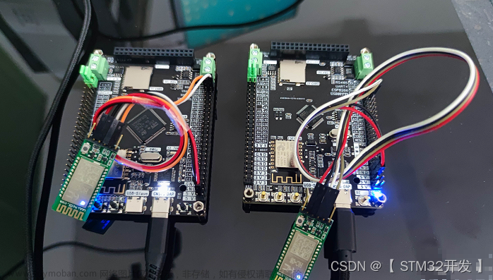
两块hc-05各连接两块stm32单片机后,两块hc-05连接之后,打开xcom或其他的一些串口软件,打开两个xcom窗口,收用一个xcom,发用一个xcom。文章来源:https://www.toymoban.com/news/detail-601805.html
 文章来源地址https://www.toymoban.com/news/detail-601805.html
四:总结:
作者能力水平有限,文章难免存在错误和纰漏,请大佬不吝赐教
到了这里,关于【基于stm32】【附代码】两块蓝牙模块HC-05进行通讯,不占用串口一的代码教程的文章就介绍完了。如果您还想了解更多内容,请在右上角搜索TOY模板网以前的文章或继续浏览下面的相关文章,希望大家以后多多支持TOY模板网!

