目录
一、实验结果
二、STM32CubeMx配置
三、main.c测试代码
一、实验结果
二、STM32CubeMx配置
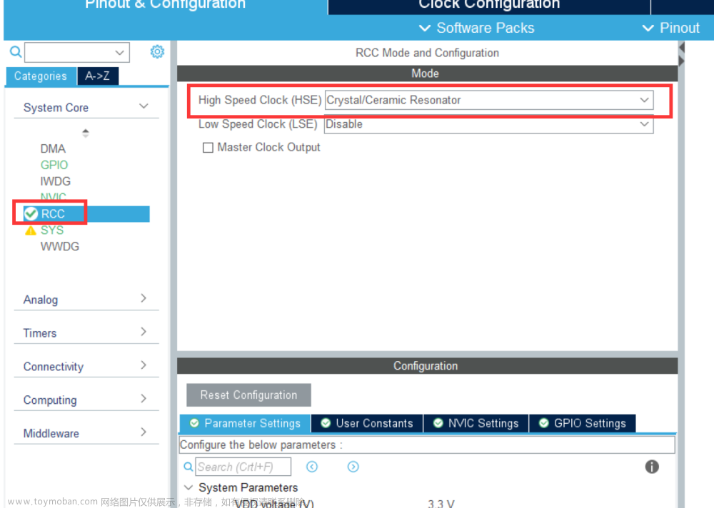
1、RCC配置

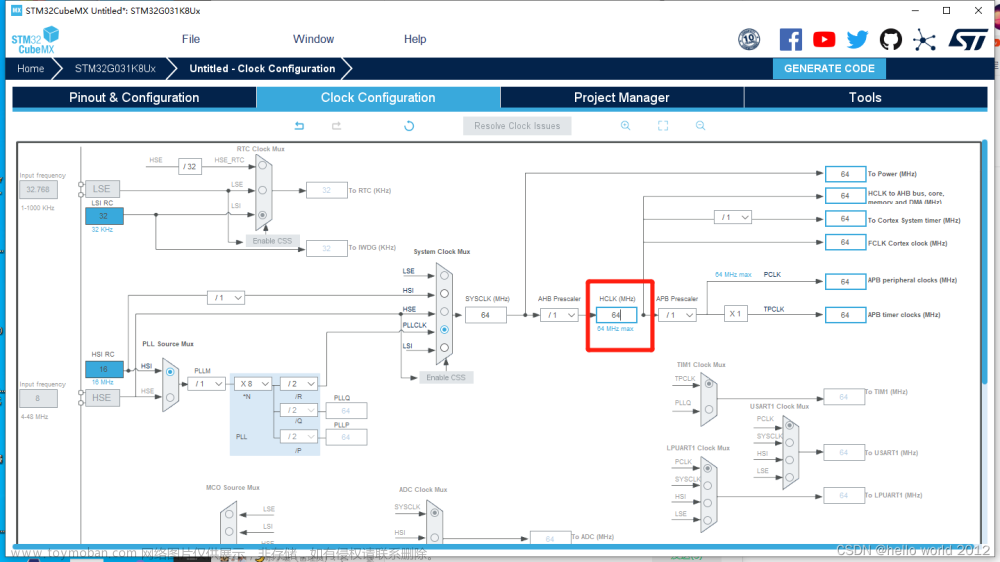
(外部晶振选择8MHz。设置相应的分频器M=8,倍频器倍频系数N=336,分频器分频系数P=2,那么主PLL生成的第一个输出高速时钟PLLP为:168MHz) 
2、SYS配置
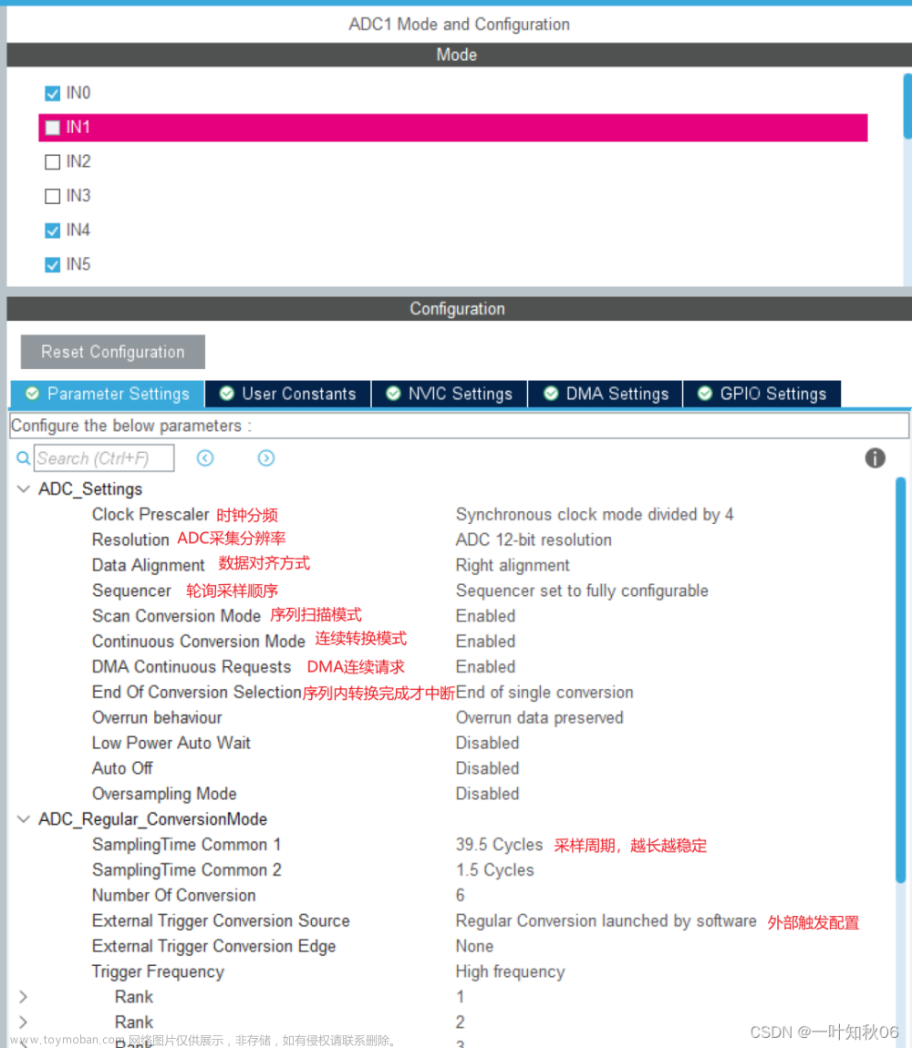
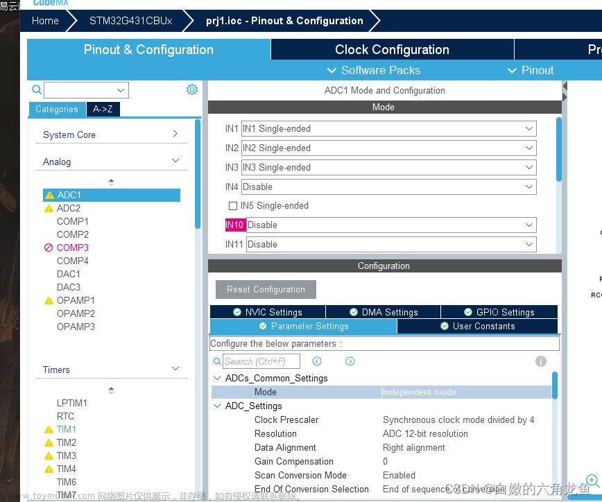
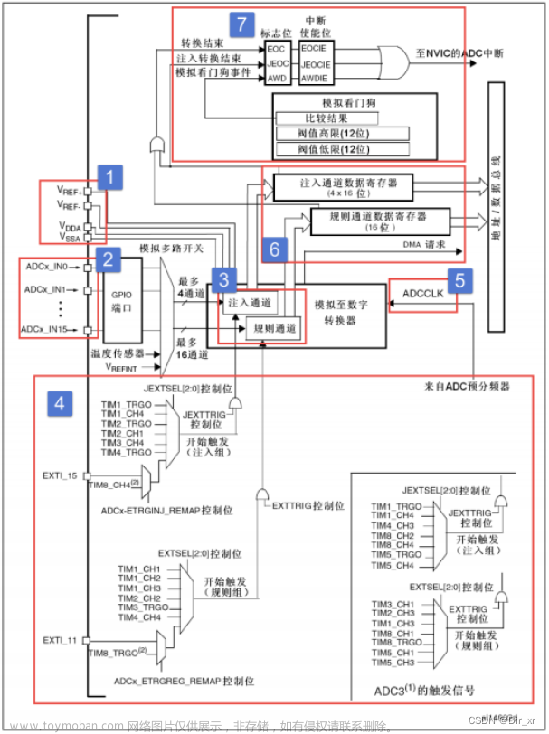
3、ADC(规则)通道配置(独立模式,预分频4分频,12位模式,扫描模式,连续转换,使能DMA,通道数3,使用软件触发)

4、DMA配置

5、串口配置

6、生成工程

7、主要代码
因为是串口输出所以要重定向USART,包含头文件<stdio.h>

usart.c中添加文章来源:https://www.toymoban.com/news/detail-612697.html
int fputc(int ch, FILE *f)
{
  HAL_UART_Transmit(&huart1, (uint8_t *)&ch, 1, 0xffff);
  return ch;
}
三、main.c测试代码
定义数组用于存放数据文章来源地址https://www.toymoban.com/news/detail-612697.html
__IO uint16_t uhADCxConvertedValue[3] = {0} ;
float VoltageValue[3] = {0};
int main(void)
{
/* MCU Configuration--------------------------------------------------------*/
/* Reset of all peripherals, Initializes the Flash interface and the Systick. */
HAL_Init();
/* Configure the system clock */
SystemClock_Config();
/* Initialize all configured peripherals */
MX_GPIO_Init();
MX_DMA_Init();
MX_ADC1_Init();
MX_USART1_UART_Init();
/* USER CODE BEGIN 2 */
printf("ADC+DMA ************ test\r\n");
HAL_ADC_Start_DMA(&hadc1,(uint32_t*)uhADCxConvertedValue,3);
printf("ADC_CHANNEL_1:%d\r\n",uhADCxConvertedValue[0]);
VoltageValue[0] = uhADCxConvertedValue[0] / (4096 * 3.3);
printf("Voltage_1:%.2f V \r\n", VoltageValue[0]);
printf("\r\nADC_CHANNEL_2:%d\r\n",uhADCxConvertedValue[1]);
VoltageValue[1] = uhADCxConvertedValue[1] / (4096 * 3.3);
printf("Voltage_2:%.2f V \r\n", VoltageValue[1]);
printf("\r\nADC_CHANNEL_3:%d\r\n",uhADCxConvertedValue[2]);
VoltageValue[2] = uhADCxConvertedValue[2] / (4096 * 3.3);
printf("Voltage_2:%.2f V \r\n", VoltageValue[2]);
/* USER CODE END 2 */
/* Infinite loop */
/* USER CODE BEGIN WHILE */
while (1)
{
}
/* USER CODE END 3 */
}到了这里,关于STM32CubeMx实现ADC多通道+DMA读取(HAL库)的文章就介绍完了。如果您还想了解更多内容,请在右上角搜索TOY模板网以前的文章或继续浏览下面的相关文章,希望大家以后多多支持TOY模板网!

