重型并串式液压机械臂建模与simscape仿真

这篇具有很好参考价值的文章主要介绍了重型并串式液压机械臂建模与simscape仿真。希望对大家有所帮助。如果存在错误或未考虑完全的地方,请大家不吝赐教,您也可以点击"举报违法"按钮提交疑问。

一、建模
Hydraulic manipulator
Figure 1 shows different constituting parts of the manipulator considered, with every part labeled using numbers from 1 to 10. For each part, a CAD model is provided. Each file is named in accordance with the corresponding label in Fig. 1 and file names are: 01 BaseGP.STEP, 02 LiftLinkGP.STEP, 03 LiftCylGP.STEP,04 LiftPistGP.STEP, 05 TiltCylGP.STEP, 06 TiltPistGP.STEP, 07 TiltLinkGP.STEP, 08 ExtCyl1GP.STEP,09 ExtPist1GP.STEP, 10 ObjectGP.STEP, respectively.
重型并串式液压机械臂建模与simscape仿真,机器人学习,并串机械臂,轨迹规划
Figure 2 shows the manipulator, conceptually divided into structures in series, as proposed in the paper.The considered manipulator can be divided into two generic manipulator structures. Structure 1 contains onlyrevolute segment, and structure 2 contains both revolute segment with passive revolute joint actuated by a linear hydraulic actuator and prismatic segment with prismatic joint, also actuated by a linear hydraulic actuator.
重型并串式液压机械臂建模与simscape仿真,机器人学习,并串机械臂,轨迹规划
Figure 3 shows the chosen set of generalized coordinates used both in the following analytic expressions and in the Simscape to command the manipulator motion.
重型并串式液压机械臂建模与simscape仿真,机器人学习,并串机械臂,轨迹规划
Manipulator structure 1
Manipulator structure 1 contains only the revolute segment from Fig.4 − 5, where the notation is inaccordance with the one proposed in the paper. Figure 5 shows the revolute segment 1 with required frames foraddressing the kinematics and dynamics. Since there is no prismatic segment, and a revolute segment follows,frames {E11} and {Bc2} are coincident, {E11} = {Bc2}, and frame {P21} does not exist in the structure 1.
重型并串式液压机械臂建模与simscape仿真,机器人学习,并串机械臂,轨迹规划
Revolute segment in the manipulator structure 1
It is assumed that linear/angular velocity vector Bc1V is known from previous calculations. Assuming fixed base, this vector is zero vector, Bc1V = 0. All the fixed distances and angles are assumed to be accurately known from CAD models and thus all the constant position vectors, as all the constant rotation matrices.
In addition, all inertia tensors and masses required for dynamics calculations can be obtained from CAD software. Exact numerical values can be found in the attached MATLAB initialization file.
Loop-closure functions
Geometric relations in the closed kinematic loop are calculated at every time instant as:重型并串式液压机械臂建模与simscape仿真,机器人学习,并串机械臂,轨迹规划
The rationale behind Eq. (4) comes from Fig. 6, with values for β
1 and β 2 found from CAD software asshown in Fig. 7 and defined in the initialization file.重型并串式液压机械臂建模与simscape仿真,机器人学习,并串机械臂,轨迹规划
重型并串式液压机械臂建模与simscape仿真,机器人学习,并串机械臂,轨迹规划
Manipulator base
The manipulator base is shown in more detail in Figure 8 with all the relevant attached frames.
Many
appropriate steps required in the modelling process will be emphasised in the manipulator base case since it is
the first to be considered. The reason for this is to avoid unnecessary repeatability, which would not introduce
much new information. The same approach, shown in more detail once, can be then later applied in the case of
every manipulator part.重型并串式液压机械臂建模与simscape仿真,机器人学习,并串机械臂,轨迹规划
重型并串式液压机械臂建模与simscape仿真,机器人学习,并串机械臂,轨迹规划
Figure 11: Manipulator base moments of inertia about the c.o.m expressed in the CAD model reference frame.重型并串式液压机械臂建模与simscape仿真,机器人学习,并串机械臂,轨迹规划
重型并串式液压机械臂建模与simscape仿真,机器人学习,并串机械臂,轨迹规划
二、simscape仿真
重型并串式液压机械臂建模与simscape仿真,机器人学习,并串机械臂,轨迹规划

仿真视频如下:

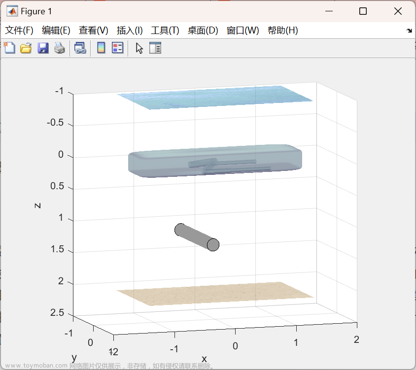
液压控制机械臂simscape仿真

下载咨询链接:matlab正逆运动学分析与轨迹规划]

源文件与仿真模型下载链接文章来源地址https://www.toymoban.com/news/detail-630565.html

到了这里,关于重型并串式液压机械臂建模与simscape仿真的文章就介绍完了。如果您还想了解更多内容,请在右上角搜索TOY模板网以前的文章或继续浏览下面的相关文章,希望大家以后多多支持TOY模板网!

本文来自互联网用户投稿,该文观点仅代表作者本人,不代表本站立场。本站仅提供信息存储空间服务,不拥有所有权,不承担相关法律责任。如若转载,请注明出处: 如若内容造成侵权/违法违规/事实不符,请点击违法举报进行投诉反馈,一经查实,立即删除!

领支付宝红包 赞助服务器费用

相关文章

  • 玩转ansys——微机械车轮的实体建模与网格化

    实验所用软件版本:ansys10.0 有限元分析的最终目的是还原一个实际工程系统的数学行为特征,即分析必须针对一个物理原型准确的数学模型。广义上讲,模型包括所有节点、单元、材料属性、实常数、边界条件,以及其他用来表现这个物理系统的特征。 建立模型的典型步骤

    2024年02月07日
    浏览(38)
  • 水下机器人双机械手系统动态建模与控制仿真(Matlab代码实现)

    ​       目录 💥1 概述 📚2 运行结果 🎉3 参考文献 👨‍💻4 Matlab代码 水下机器人-机械手系统(Underwater vehicle-manipulator systems, UVMS)可以完成除观测之外的水下采样、抓取、操作等任务,在海洋科学考察、海洋工程等领域得到广泛应用。通过对近年来国内外UVMS的研究现状

    2024年02月08日
    浏览(53)
  • 六自由度机器人(机械臂)运动学建模及运动规划系列(一)——简介

    毕业设计做了六轴机器人相关的课题,做完之后学到很多,在这里分享一下。本篇首先对六轴机器人及其研究内容进行简单的介绍。 六轴机器人中的六轴指个六自由度,由关节和连杆组成。常见的六轴机器人为 串联型旋转关节机器人 。这里以一款川崎机器人为例,展示一下

    2024年02月02日
    浏览(45)
  • 六自由度机器人(机械臂)运动学建模及运动规划系列(四)——轨迹规划

    对机器人进行轨迹规划的主要任务是,根据机器人的工作环境和工作任务要求,求得一系列机器人末端位姿变换的时间序列,使得机器人末端可以正确地从初始姿态沿着期望的轨迹运动到终止位姿,完成工作任务,。对于六自由度的机器人来说,轨迹规划要解决的关键问题是

    2024年02月03日
    浏览(67)
  • 【机器人1】基于POE公式的UR5机械臂正运动学建模求解与matlab仿真

    下一篇:【机器人2】基于POE公式的UR5机械臂逆运动学建模求解与matlab仿真 螺旋轴表示成:绕某个轴的转动与沿该轴的移动的复合。一种形式是 { q , s ^ , h } {boldsymbol{q}, boldsymbol{hat{s}}, h} { q , s ^ , h } : 其中, q ∈ R 3 boldsymbol{q} in mathbb{R}^{3} q ∈ R 3 为轴上任一点; s ^

    2024年02月06日
    浏览(84)
  • 用verilog 实现8bit数据的并串转换

    输入信号为8bit并行信号 该程序实现每8个时钟周期,便把收到的8bit并行信号拆解成串行信号并输出,等下8个时钟周期过后再转换下一个并行信号。 仿真图如下:

    2024年02月15日
    浏览(39)
  • Matlab/simulink/simscape multibody-to wotkspace模块使用

    因工作需要,对于Matlab/simulink的需求越来越大,学过但不记录就如走马观花,既然如此,那就学在这里,记在这里。下面以simulink中to workspace块为主,以scope块 和 timeseries数据使用为辅的一种使用方法记录。 一句话,to workspace块的功能是把simulink环境生成的数据直接导入到Ma

    2024年02月06日
    浏览(38)
  • LabVIEW与微信开发数字液压缸测控系统

    针对传统煤矿液压支架控制存在的精度和直线度问题,设计了一种数字液压缸测控系统,其核心是LabVIEW软件与微信小程序的结合,以及对应的精准硬件配置。该系统使用了NI CDAQ 9189数据采集控制器、脉冲输出模块和多种传感器(MIK-P300压力传感器和MPS-S-1000拉线位移传感器),

    2024年01月19日
    浏览(38)
  • LabVIEW 智能化矿用定向钻机液压系统监测

      简介  在矿用定向钻机的液压系统监测中,实现实时监控和异常预警对于保障设备运行的稳定性至关重要。传统的人工监测方法效率低下而且准确性不能满足要求,针对这种情况采用 LabVIEW 开发平台,设计并实现了一套智能化矿用定向钻机液压系统的状态监测系统。该系

    2024年02月02日
    浏览(38)
  • 机器人学|手机玻璃加工全自动化——AGV+机器人+视觉解决方案(含双目三维视觉SLAM建图、MATLAB的AGV路径规划导航避障、六轴机械手臂建模与路径规划仿真,附带源代码)

    文章目录 前言 一、国内外移动操作机器人现状 二、方案概述 三、主要部件BOM清单 1.差动轮式AGV: 2.UR5系列机械臂 3.Cognex智能相机 4.加工台 5.控制系统 6.电源和电缆 四、技术点及工作流程 五、计算自动化方案与人工方案成本收回时间 1.自动化方案成本分析: 2.人工方案成本

    2024年01月22日
    浏览(48)

觉得文章有用就打赏一下文章作者

支付宝扫一扫打赏

博客赞助

微信扫一扫打赏

请作者喝杯咖啡吧~博客赞助

支付宝扫一扫领取红包,优惠每天领

二维码1

领取红包

二维码2

领红包