一、模块与端口
1、模块
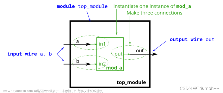
Verilog进行FPGA/IC设计值,通常划分为各个子模块,木模块之间可能相互例化,并在顶层统一例化,并连接成一个顶层模块文件。
基本的模块模板:
module module_name(
	input i_clk,
	input i_a,
	input [3:0] i_b,
	input i_en,
	output o_out,
	inout [3:0] o_c
	//your input/ouput/inout ports
);

//your sequential logic
always@(posedge i_clk) begin
//your sequential logic
end

//your combinational logic
always@(*) begin
//your logic
end

assign o_c = i_en ? i_b : 4'hz;
//......

//institation other module
a_module inst(
.i_clk(i_clk),
.i_a(i_a),
.o_c(o_c),
);

endmodule
如果模块内的变量位宽参数化,则模块模板为:
module exam_module
#(
parameter c_WIDTH = 8,
parameter c_DEPTH = 16
)(
//input
input i_a,
//inout
inout io_b,
//output
output o_c
);

//the same as before module
endmodule
例化带参数的模块:
module top_module(
// input/output/inout ports define
);

//other logics

//institation module with parameter
exam_module
#(
.c_WIDTH(8),
.c_DEPTH(6)
)inst0(
//ports parts
);

endmodule
2、端口
端口类型/端口描述
- input 设计模块只能使用其input端口从外部接收值
- output 设计模块只能使用其output端口将值发送到外部
- inout设计模块可以使用其inout端口发送或接收值
module  my_design ( input wire      clk,
                    input           en,
                    input           rw,
                    inout [15:0]    data,
                    output           int );

  // Design behavior as Verilog code
endmodule
关于模块端口的说明
当不定义端口数据类型时,默认为wire型,端口名不能重复,需要存储值的输出端口应该声明为 reg 数据类型,并且可以在程序块中使用,比如 always 和 initial only。
输入或inout类型的端口不能声明为reg,因为它们是由外部连续驱动的,不应该存储值,而是尽快反映外部信号的变化。连接两个不同向量大小的端口是完全合法的,但以向量大小较小的端口为准,而另一个宽度较大的端口的剩余位将被忽略。
有符号端口声明
可以使用signed属性来声明有符号端口,默认情况下是无符号的端口。
 module (
           input signed a, b,  // a, b are signed from port declaration
           output reg signed c // c is signed from reg declaration
           );

  endmodule
2001年verilog修订:模块端口声明:
module test ( input [7:0]  a,
                            b,     // "b" is considered an 8-bit input
              output [7:0]  c);

  // Design content
endmodule

module test ( input wire [7:0]  a,
              input wire [7:0]  b,
              output reg [7:0]  c);

  // Design content
endmodule
- 如果端口声明包含网络或变量类型,则认为该端口已完全声明。在网络或变量类型声明中重新声明相同的端口是非法的。
module test ( input      [7:0] a,       // a, e are implicitly declared of type wire
            output reg [7:0] e );

   wire signed [7:0] a;     // illegal - declaration of a is already complete -> simulator dependent
   wire        [7:0] e;     // illegal - declaration of e is already complete

   // Rest of the design code
endmodule
- 如果端口声明不包含网络或变量类型,则可以再次在网络或变量类型声明中声明端口
module test ( input      [7:0] a,
              output     [7:0] e);

     reg [7:0] e;              // Okay - net_type was not declared before

     // Rest of the design code
endmodule
二、模块例化与端口处理
Verilog例化方式分为两种,一种是按端口定义时的顺序例化,一种是按端口名来例化。
举例说明:
首先给出一个模块端口:
module mydesign ( input  x, y, z,     // x is at position 1, y at 2, x at 3 and
                  output o);          // o is at position 4

endmodule
- 按端口排序顺序例化
  module tb_top;
    wire [1:0]  a;
    wire        b, c;

    mydesign d0  (a[0], b, a[1], c);  // a[0] 连接 x
                                      // b 连接 y
                                      // a[1] 连接 z
                                      // c 连接  o
  endmodule
- 按端口名例化
  module tb_top;
    wire [1:0]  a;
    wire        b, c;
	mydesign d0(
	.x(a[0]),
	.y(b),
	.z(a[1]),
	.o(c)
	);
  endmodule
未连接/悬空端口处理
未连接到例化模块中的端口按高阻态处理。如下:
module design_top(
	input [1:0] a,
	output c
);
  mydesign d0   (              // x 没有写, a[0] = Z 以高阻态显示
                .y (a[1]),
                .z (a[1]),
                .o ());        // o 虽然写了,但是没有连接任何端口信号,
                               // it is not connected to "c" in design_top, c will be Z
endmodule
端口x,就连写都没写,因此,可以认为是一个未连接的悬空端口,是一个高阻态;
端口o,虽然写了,但是也没连接到顶层模块中的任意一个端口上,因此顶层的端口c也是一个高阻态。
例如:
触发器:
// Module called "dff" has 3 inputs and 1 output port
module dff (   input       d,
              input       clk,
              input       rstn,
              output reg  q);

  // Contents of the module
  always @ (posedge clk) begin
    if (!rstn)
      q <= 0;
    else
      q <= d;
  end
endmodule
当所有端口都有效连接时:
module shift_reg (   input   d,
                    input    clk,
                    input   rstn,
                    output   q);

  wire [2:0] q_net;
  dff u0 (.d(d),        .clk(clk), .rstn(rstn), .q(q_net[0]));
  dff u1 (.d(q_net[0]), .clk(clk), .rstn(rstn), .q(q_net[1]));
  dff u2 (.d(q_net[1]), .clk(clk), .rstn(rstn), .q(q_net[2]));
  dff u3 (.d(q_net[2]), .clk(clk), .rstn(rstn), .q(q));

endmodule
RTL原理图:
当有些端口未连接时:
module shift_reg (   input   d,
                    input    clk,
                    input   rstn,
                    output   q);

  wire [2:0] q_net;

  dff u0 (.d(d),        .clk(clk), .rstn(rstn), .q(q_net[0]));
  dff u1 (.d(q_net[0]), .clk(clk), .rstn(rstn), .q());             // Output q is left floating
  dff u2 (.d(q_net[1]), .clk(clk), .rstn(rstn), .q());             // Output q is left floating
  dff u3 (.d(q_net[2]), .clk(clk), .rstn(rstn), .q(q));

endmodule
RTL原图:
对其进行仿真,由于短口味连接即悬空了,输出为高阻态z文章来源:https://www.toymoban.com/news/detail-643913.html
 文章来源地址https://www.toymoban.com/news/detail-643913.html
到了这里,关于Verilog基础语法(4)之模块和端口及其例化和处理的文章就介绍完了。如果您还想了解更多内容,请在右上角搜索TOY模板网以前的文章或继续浏览下面的相关文章,希望大家以后多多支持TOY模板网!


![Verilog语法-模块module[Day2学习笔记]](https://imgs.yssmx.com/Uploads/2024/02/608941-1.png)


