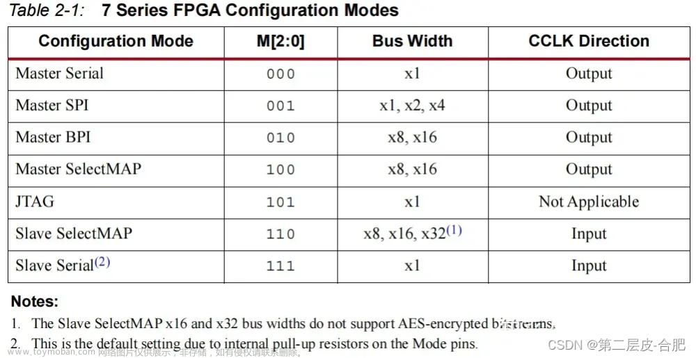
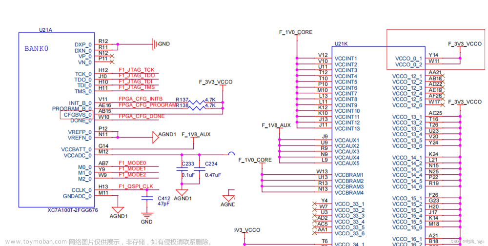
本文针对单从设备SelectMAP配置过程进行说明,希望作者本人走过的坑,你们可以不用走。
首先SelectMAP的硬件连接原理参考官网ug470手册说明,信号状态保证一致(数据位可选择x8、x16、x32,作者本人使用的x8),如下图所示:

配置时序参考官网给出的连续8位SelectMAP数据加载方式;
从图中可以看出,在配置过程中,首先拉低PROGRAM_B信号,被配置的FPGA检测到PROGRAM信号拉低后,会将INIT_B信号拉低。这个时候就可以拉高PROGRAM_B信号,等待INIT_B信号变高,就可以开始写入配置数据(CCLK上升沿锁存数据)。特别注意:配置数据写完以后还要继续发时钟,FPGA的内部还需要时钟做一些工作,等待DONE信号拉高以后就可以正常使用了。

从图中还可以看出,CSI_B和RDWR_B可以一直是低电平。因为FPGA的bin文件中有帧头等等一些数据,可以不用在需要的时候才拉低信号。

上程序,看设计思路:
module ConfigurationStream(
input CLK,
input RSTn,
input CFG_START_VALID, //上电检测flash标志,有配置数据则开始配置
input FLASH_READ_DONE,//flash读取到一个字节的配置数据
output FLASH_START_LOAD,//开始让flash读取配置数据
input [7:0] FLASH_DATA, //flash读取到的数据
output program_b,
input init_b,
output [7:0] dataout,
output csi_b,
output rdwr_b,
output cclk,
input done
);
parameter CFG_IDLE = 4'd0,
CFG_START = 4'd1,
WAIT_INIT = 4'd2,
CFG_PREPARE = 4'd3,
LOAD_STREAM = 4'd4,
SEND_STREAM = 4'd5,
WAIT_DONE = 4'd6,
CFG_FINISH = 4'd7;
reg [3:0] state;
reg program_r,csi_r,rdwr_r,cclk_r,start_load_r;
reg [7:0] dataout_r;
reg [25:0] byte_size;
reg [31:0] counter;
assign program_b = program_r;
assign dataout = dataout_r;
assign csi_b = csi_r;
assign rdwr_b = rdwr_r;
assign cclk = cclk_r;
assign FLASH_START_LOAD = start_load_r;
reg cfg_start_valid_r;
wire CFG_VALID;
assign CFG_VALID = CFG_START_VALID & (~cfg_start_valid_r);
always @(posedge CLK or negedge RSTn)
if(!RSTn) begin
cfg_start_valid_r <= 1'b0;
end else begin
cfg_start_valid_r <= CFG_START_VALID;
end
always @(posedge CLK or negedge RSTn)
if(!RSTn) begin
program_r <= 1'b1;
dataout_r <= 8'h00;
//csi_r <= 1'b1;
//rdwr_r <= 1'b1;
//cclk_r <= 1'b1;
csi_r <= 1'b0;
rdwr_r <= 1'b0;
cclk_r <= 1'b0;
byte_size <= 26'd0;
counter <= 32'd0;
start_load_r <= 1'b0;
state <= CFG_IDLE;
end else begin
case(state)
CFG_IDLE: if(CFG_VALID == 1'b1) begin
state <= CFG_START;
end else begin
program_r <= 1'b1;
dataout_r <= 8'h00;
//csi_r <= 1'b1;
//rdwr_r <= 1'b1;
//cclk_r <= 1'b1;
csi_r <= 1'b0;
rdwr_r <= 1'b0;
cclk_r <= 1'b0;
byte_size <= 26'd0;
state <= CFG_IDLE;
end
CFG_START: if(counter < 32'd40000) begin //program_B toggle
program_r <= 1'b0;
counter <= counter + 1'b1;
state <= CFG_START;
end else begin
counter <= 32'd0;
program_r <= 1'b1;
state <= WAIT_INIT;
end
WAIT_INIT: if(init_b == 1'b1) begin
start_load_r <= 1'b1;
state <= CFG_PREPARE;
end else begin
state <= WAIT_INIT;
end
CFG_PREPARE: begin
rdwr_r <= 1'b0;
start_load_r <= 1'b0;
state <= LOAD_STREAM;
end
LOAD_STREAM: if(FLASH_READ_DONE) begin
counter <= 32'd0;
state <= SEND_STREAM;
end else begin
if(counter > 32'd200000) begin
counter <= 32'd0;
state <= CFG_FINISH;
end else begin
counter <= counter + 1'b1;
state <= LOAD_STREAM;
end
end
SEND_STREAM: if(byte_size < 26'h947a5c) begin
if(counter == 32'd0) begin
csi_r <= 1'b0;
cclk_r <= 1'b0;
counter <= counter + 1'b1;
dataout_r <= FLASH_DATA;
end else if(counter == 32'd5) begin
cclk_r <= 1'b1;
byte_size <= byte_size + 1'b1;
state <= LOAD_STREAM;
end else begin
counter <= counter + 1'b1;
end
end else begin
state <= WAIT_DONE;
end
WAIT_DONE: if(counter == 32'd0) begin
cclk_r <= 1'b0;
counter <= counter + 1'b1;
end else if(counter == 32'd5) begin
cclk_r <= 1'b1;
counter <= counter + 1'b1;
end else if(counter == 32'd9) begin
if(done) begin
state <= CFG_FINISH;
end else begin
state <= WAIT_DONE;
end
counter <= 32'd0;
end else begin
counter <= counter + 1'b1;
end
CFG_FINISH: begin
program_r <= 1'b1;
csi_r <= 1'b1;
rdwr_r <= 1'b1;
cclk_r <= 1'b1;
state <= CFG_FINISH;
end
default: state <= CFG_IDLE;
endcase
end
endmodule
实测波形分别如下:
- 测量波形


配置完以后,结果发现FPGA没有启动,百思不得其解。研究半天,突然灵感来了,想起来配置的数据是反的,怎么反?上图。
 文章来源:https://www.toymoban.com/news/detail-713370.html
从图中可以看到,配置数据的高位在D0,数据低位在D7。就把引脚定义改了一下,一把成,堪称完美!👏👏👏文章来源地址https://www.toymoban.com/news/detail-713370.html
到了这里,关于XILINX FPGA SelectMAP方式配置过程说明的文章就介绍完了。如果您还想了解更多内容,请在右上角搜索TOY模板网以前的文章或继续浏览下面的相关文章,希望大家以后多多支持TOY模板网!


