一、前言
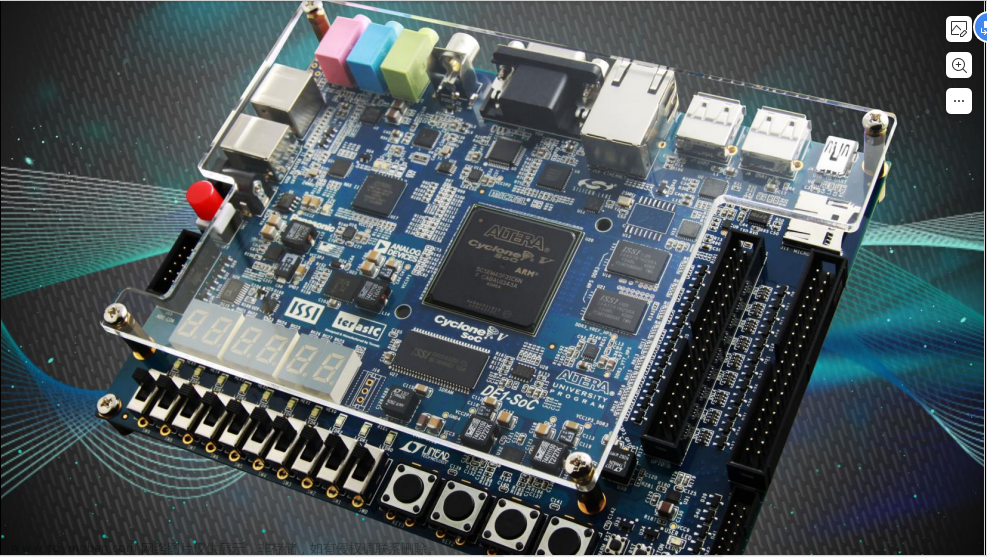
本文利用verilog语言完成频率计实验,由于是第一次发文,文章格式以及描述语言请谅解,内容仅供参考,烦请各路大神指正。
二、模块
- 数码管动态显示模块
- 分频模块
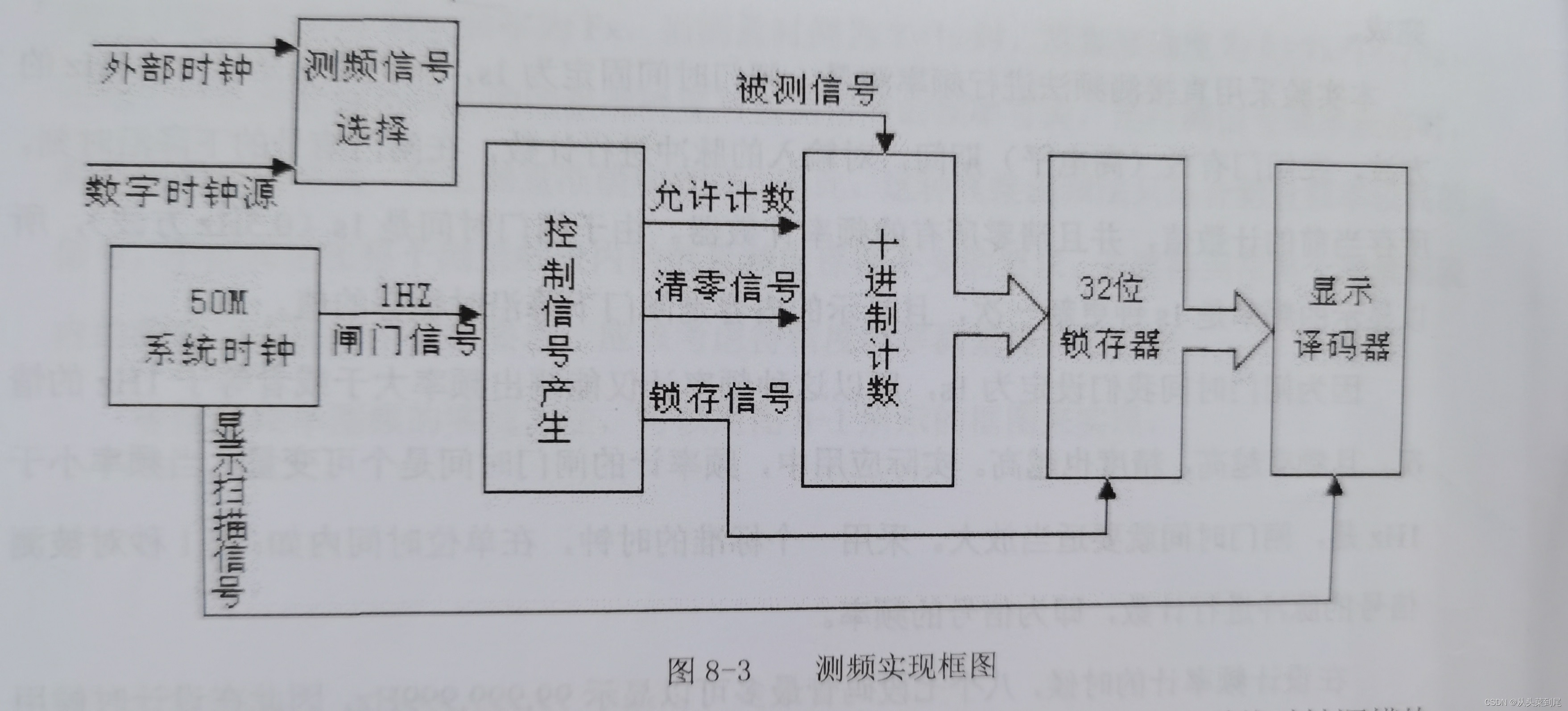
- 频率测试模块
- 顶层调用模块
三、主要代码
1、数码管动态显示模块
module seg_led(
input clk,
input rst_n,
input [19:0] data,//6个数码管最高显示999999,需要20位
input [5:0] point,//小数点
input sign,//负号
input en,
output reg [7:0] seg_data,//数码管显示的笔画值
output reg [5:0] seg_sel
);wire [3:0] data0;//个位
wire [3:0] data1;//十位
wire [3:0] data2;//百位
wire [3:0] data3;//千位
wire [3:0] data4;//万位
wire [3:0] data5;//十万位reg [3:0] clk_cnt;
reg dri_clk;
reg [23:0] num;
reg [12:0] cnt0;
reg flag;
reg [2:0] cnt_sel;
reg [3:0] num_disp;
reg dot_disp;parameter CLK_DIVIDE = 4'd10;
parameter MCNT = 13'd5_000;assign data0 = data%4'd10;//每个数码管取模运算
assign data1 = data/4'd10%4'd10;
assign data2 = data/7'd100%4'd10;
assign data3 = data/10'd1000%4'd10;
assign data4 = data/14'd10000%4'd10;
assign data5 = data/17'd100000;always@(posedge clk or negedge rst_n)begin
if(!rst_n)begin
clk_cnt <= 4'b0;
dri_clk <= 1'b1;
end
else if(clk_cnt == CLK_DIVIDE/2-1'b1)begin
clk_cnt <= 4'b0;
dri_clk <= ~dri_clk;
end
else begin
clk_cnt <= clk_cnt + 1'b1;
dri_clk <= dri_clk;
end
endalways@(posedge dri_clk or negedge rst_n)begin
if(!rst_n)
num <= 24'd0;
else begin
if(data5||point[5])begin
num[23:20]<=data5;
num[19:16]<=data4;
num[15:12]<=data3;
num[11:8]<=data2;
num[7:4]<=data1;
num[3:0]<=data0;
end
else begin
if(data4||point[4])begin
num[19:0]<={data4,data3,data2,data1,data0};
if(sign)
num[23:20]<=4'd11;
else
num[23:20]<=4'd10;
end
else begin
if(data3||point[3])begin
num[15:0]<={data3,data2,data1,data0};
num[23:20]<=4'd10;
if(sign)
num[19:16]<=4'd11;
else
num[19:16]<=4'd10;
end
else begin
if(data2||point[2])begin
num[11:0]<={data2,data1,data0};
num[23:16]<={2{4'd10}};
if(sign)
num[15:12]<=4'd11;
else
num[15:12]<=4'd10;
end
else begin
if(data1||point[1])begin
num[7:0]<={data1,data0};
num[23:12]<={3{4'd10}};
if(sign)
num[11:8]<=4'd11;
else
num[11:8]<=4'd10;
end
else begin
num[3:0]<={data2,data1,data0};
num[23:8]<={4{4'd10}};
if(sign)
num[7:4]<=4'd11;
else
num[7:4]<=4'd10;
end
end
end
end
end
end
endalways@(posedge dri_clk or negedge rst_n)begin
if(!rst_n)begin
cnt0 <= 13'b0;
flag <= 1'b0;
end
else if(cnt0 == MCNT - 1)begin
cnt0 <= 13'b0;
flag <= 1'b1;
end
else begin
cnt0 <= cnt0 + 13'b1;
flag <= 1'b0;
end
endalways@(posedge dri_clk or negedge rst_n)begin
if(!rst_n)
cnt_sel <= 3'b0;
else if(flag)
begin
if(cnt_sel < 3'd5)
cnt_sel <= cnt_sel + 1'b1;
else
cnt_sel <= 3'b0;
end
else
cnt_sel <= cnt_sel;
endalways@(posedge dri_clk or negedge rst_n)
begin
if(!rst_n)
begin
seg_sel <= 6'b11_1111;
num_disp <= 4'b0;
dot_disp <= 1'b0;
end
else
begin
if (en)
begin
case(cnt_sel)
3'd0 :begin
seg_sel <= 6'b11_1110;
num_disp <= num[3:0];
dot_disp <= ~point[0];
end
3'd1 :begin
seg_sel <= 6'b11_1101;
num_disp <= num[7:4];
dot_disp <= ~point[1];
end
3'd2 :begin
seg_sel <= 6'b11_1011;
num_disp <= num[11:8];
dot_disp <= ~point[2];
end
3'd3 :begin
seg_sel <= 6'b11_0111;
num_disp <= num[15:12];
dot_disp <= ~point[3];
end
3'd4 :begin
seg_sel <= 6'b10_1111;
num_disp <= num[19:16];
dot_disp <= ~point[4];
end
3'd5 :begin
seg_sel <= 6'b01_1111;
num_disp <= num[23:20];
dot_disp <= ~point[5];
end
default :begin
seg_sel <= 6'b11_1111;
num_disp <= 4'b0;
dot_disp <= 1'b1;
end
endcase
end
else begin
seg_sel <= 6'b11_1111;
num_disp <= 4'b0;
dot_disp <= 1'b1;
end
end
endalways@(posedge dri_clk or negedge rst_n)
begin
if(!rst_n)
seg_data <= 8'hc0;
else
begin
case(num_disp)
4'd0 : seg_data <= {dot_disp,7'b100_0000};
4'd1 : seg_data <= {dot_disp,7'b111_1001};
4'd2 : seg_data <= {dot_disp,7'b010_0100};
4'd3 : seg_data <= {dot_disp,7'b011_0000};
4'd4 : seg_data <= {dot_disp,7'b001_1001};
4'd5 : seg_data <= {dot_disp,7'b001_0010};
4'd6 : seg_data <= {dot_disp,7'b000_0010};
4'd7 : seg_data <= {dot_disp,7'b111_1000};
4'd8 : seg_data <= {dot_disp,7'b000_0000};
4'd9 : seg_data <= {dot_disp,7'b001_0000};
4'd10 : seg_data <= {8'b1111_1111};
4'd11 : seg_data <= {8'b1011_1111};
default:
seg_data<={dot_disp,7'b100_0000};
endcase
end
end
endmodule
2、频率测试模块
module cymometer(
input clk,
input rst_n,
input clk_fx,
output reg [31:0] fre
);
parameter TIME_SYS = 20;
parameter TIME_GATE = 500_000_000;
localparam N = TIME_GATE / TIME_SYS;
reg gate;
reg [31:0] cnt_gate;
reg [31:0] cnt_fx;
wire gate_n;
assign gate_n = ~gate;
always @(posedge clk or negedge rst_n)begin
if(!rst_n)begin
cnt_gate <=0;
gate <=0;
end
else begin
if(cnt_gate == N-1)begin
cnt_gate <= 0;
gate <= ~gate;
end
else
cnt_gate<=cnt_gate+1;
end
end
always @(posedge clk_fx or negedge rst_n)begin
if(!rst_n)
cnt_fx <= 0;
else if(gate)
cnt_fx <= cnt_fx + 1;
else
cnt_fx <= 0;
end
always @(posedge gate_n or negedge rst_n)begin
if(!rst_n)
fre <= 0;
else
fre <= 1000_000_000/TIME_GATE * cnt_fx;
end
endmodule
3、分频模块
module test_div(
input clk,
input rst_n,
output reg div_clk
);reg [9:0]clk_cnt;
parameter CLK_DIVIDE = 7'd100;always @(posedge clk or negedge rst_n)begin
if(!rst_n) begin
clk_cnt <= 10'd0;
div_clk <= 1'b0;
end
else if(clk_cnt == CLK_DIVIDE/2 - 1'd1)begin
clk_cnt <= 10'd0;
div_clk <= ~div_clk;
end
else begin
clk_cnt <= clk_cnt + 1'b1;
div_clk <= div_clk;
end
endendmodule
四、总结
通过以上代码,最后完成顶层调用模块,再分配引脚,即可完成实验。
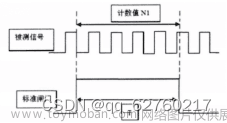
分频模块对系统时钟进行100分频(500KHZ)输入给频率测量模块,通过周期测量法在数码管中显示5000000。(自己产生频率自己测量)
五、图片


 文章来源:https://www.toymoban.com/news/detail-735844.html
由于本人初学fgpa有很多困难并未解决,代码虽然可以运行但可能并不是最优,本文仅用于记录自己的学习历程以及实验总结,烦请各位指正以及交流,欢迎各位私信交流。文章来源地址https://www.toymoban.com/news/detail-735844.html
到了这里,关于FPGA(verilog)频率计实验——学习历程①的文章就介绍完了。如果您还想了解更多内容,请在右上角搜索TOY模板网以前的文章或继续浏览下面的相关文章,希望大家以后多多支持TOY模板网!


