目录
实验原理
源代码
仿真代码
管脚配置
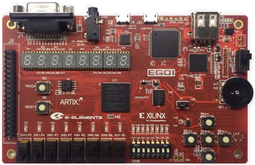
实验板卡:xc7a100tlc sg324-2L,共20个开关
实验原理


源代码
顶层模块
`timescale 1ns / 1ps

module Four_Bits_Lookahead_Adder(a,b,cin,S,C);
    input [3:0] a;
    input [3:0] b;
    input cin;
    output [3:0] S;
    output C;
    wire [4:1] c;
    wire drop;

    Lookahead uut(a,b,cin,c);
    assign C=c[4];
    Full_Adder u1(a[0],b[0],cin,S[0],drop);
    Full_Adder u2(a[1],b[1],c[1],S[1],drop);
    Full_Adder u3(a[2],b[2],c[2],S[2],drop);
    Full_Adder u4(a[3],b[3],c[3],S[3],drop);
endmodule
超前进位模块
`timescale 1ns / 1ps

module Lookahead(a,b,cin,C);
    input [3:0] a;
    input [3:0] b;
    input cin;
    output [4:1] C;
    wire [3:0] G;
    wire [3:0] P;

    assign G[0]=a[0]&b[0];
    assign G[1]=a[1]&b[1];
    assign G[2]=a[2]&b[2];
    assign G[3]=a[3]&b[3];

    assign P[0]=a[0]|b[0];
    assign P[1]=a[1]|b[1];
    assign P[2]=a[2]|b[2];
    assign P[3]=a[3]|b[3];

    assign C[1]=G[0]|(P[0]&cin);
    assign C[2]=G[1]|(P[1]&G[0])|(P[1]&P[0]&cin);
    assign C[3]=G[2]|(P[2]&G[1])|(P[2]&P[1]&G[0])|(P[2]&P[1]&P[0]&cin);
    assign C[4]=G[3]|(P[3]&G[2])|(P[3]&P[2]&G[1])|(P[3]&P[2]&P[1]&G[0])|(P[3]&P[2]&P[1]&P[0]&cin);
endmodule全加器模块文章来源:https://www.toymoban.com/news/detail-736162.html
`timescale 1ns / 1ps

module Full_Adder(a,b,cin,S,C);
    input a,b,cin;
    output S,C;
    wire S1,T1,T2,T3;
xor
    X1(S1,a,b),
    X2(S,S1,cin);

and
    A1(T3,a,b),
    A2(T2,b,cin),
    A3(T1,a,cin);

or
    O1(C,T1,T2,T3);
endmodule
仿真代码
`timescale 1ns / 1ps

module sim_Four_Lookahead_Adder();
    reg [3:0] a;
    reg [3:0] b;
    reg cin;
    wire [3:0] S;
    wire C;
    Four_Bits_Lookahead_Adder uut(
        a[3:0],
        b[3:0],
        cin,
        S[3:0],
        C
        );
    initial begin
        a[3:0]=0;
        b[3:0]=0;
        cin=0;
    end
    always
    #10
    {a[3],a[2],a[1],a[0],b[3],b[2],b[1],b[0],cin}={a[3],a[2],a[1],a[0],b[3],b[2],b[1],b[0],cin}+1;
endmodule
管脚配置
注:vivado版本为2018版,板卡为xc7a100tlcsg324-2L文章来源地址https://www.toymoban.com/news/detail-736162.html
set_property -dict {IOSTANDARD LVCMOS18 PACKAGE_PIN V5} [get_ports a[3]]
set_property -dict {IOSTANDARD LVCMOS18 PACKAGE_PIN T4} [get_ports a[2]]
set_property -dict {IOSTANDARD LVCMOS18 PACKAGE_PIN V6} [get_ports a[1]]
set_property -dict {IOSTANDARD LVCMOS18 PACKAGE_PIN T5} [get_ports a[0]]
set_property -dict {IOSTANDARD LVCMOS18 PACKAGE_PIN T6} [get_ports b[3]]
set_property -dict {IOSTANDARD LVCMOS18 PACKAGE_PIN V7} [get_ports b[2]]
set_property -dict {IOSTANDARD LVCMOS18 PACKAGE_PIN R8} [get_ports b[1]]
set_property -dict {IOSTANDARD LVCMOS18 PACKAGE_PIN U9} [get_ports b[0]]
set_property -dict {IOSTANDARD LVCMOS18 PACKAGE_PIN T9} [get_ports cin]
set_property -dict {IOSTANDARD LVCMOS18 PACKAGE_PIN U6} [get_ports C]
set_property -dict {IOSTANDARD LVCMOS18 PACKAGE_PIN R5} [get_ports S[3]]
set_property -dict {IOSTANDARD LVCMOS18 PACKAGE_PIN U7} [get_ports S[2]]
set_property -dict {IOSTANDARD LVCMOS18 PACKAGE_PIN R6} [get_ports S[1]]
set_property -dict {IOSTANDARD LVCMOS18 PACKAGE_PIN R7} [get_ports S[0]]
到了这里,关于【基于FPGA的芯片设计】4位超前进位加法器的文章就介绍完了。如果您还想了解更多内容,请在右上角搜索TOY模板网以前的文章或继续浏览下面的相关文章,希望大家以后多多支持TOY模板网!


![[FPGA]用Verilog写一个简单三位二进制加法器和减法器](https://imgs.yssmx.com/Uploads/2024/02/761556-1.png)


