STM32 内部FLAsh概述
今天说一下STM32中的内部flash。
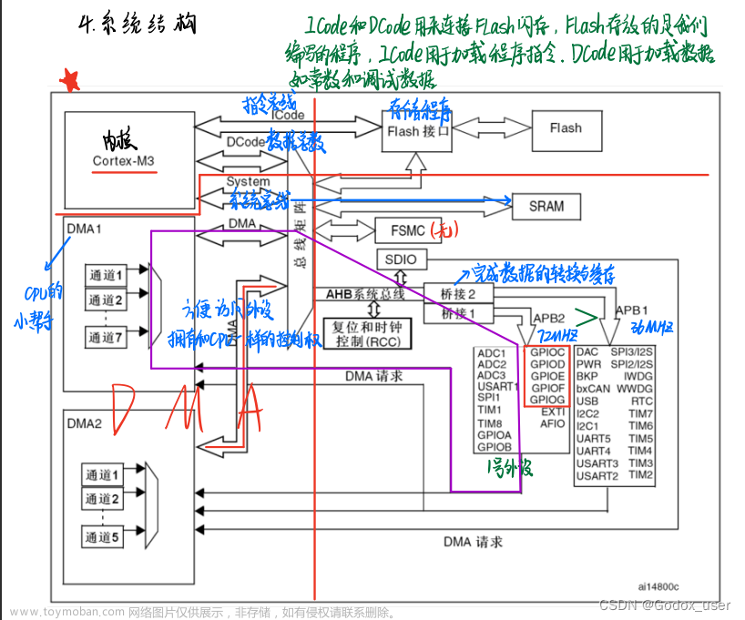
当我们把写好的代码下载MCU中,这个代码时存放在flash中的。当芯片重启复位上电后,会通过内核对flash进行代码的加载运行。大致是这个过程。
主要特性
- flash读操作
- flash编程/擦除操作
- 读写保护
- I-Code 上的预取操作
- I-Code 上的 64 个缓存(128 位宽)
- D-Code 上的 8 个缓存(128 位宽)
- 128 位宽数据读取
- 字节、半字、字和双字数据写入
- 扇区擦除与全部擦除

除了程序下载对自身flash读写外,本身也可以通过软件编程对其进行书写,可进行一些数据的存储。
下面就说一下这方面的东西(当然不同的芯片flash有所不同,这里以STM32F429进行介绍,其他芯片即使厂商不同,但是大致的流程和功能是一样的。)
内部FLASH的结构
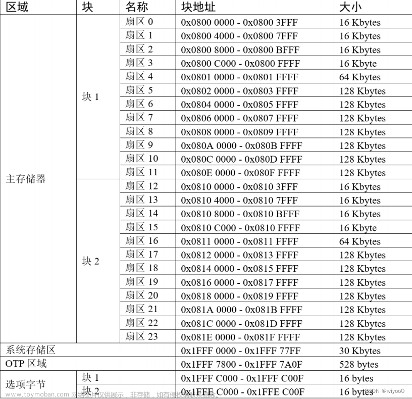
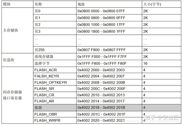
根据数据手册来看,STM32的内部FLASH有主存储器、系统存储器、OTP区域以及选项字节区域。如图
-
主存储器:在STM32F4中共有12个主存储器扇区,这12个扇区分为4个16KB、1个64KB以及7个128KB扇区。
-
系统存储器:器件在系统存储器自举模式下从该存储器启动(就是boot代码,出厂就已经存在的,专门给主存储器下载代码用的,这时候B0外接3.3V,B1接GND的时候从写个存储器启动(像CAN、串口下载就用这个)。
-
OTP 区域:即一次性可编程区域,共 528 字节,被分成两个部分,前面 512 字节(32 字节为 1 块,分成 16 块),可以用来存储一些用户数据(一次性的,写完一次,永远不可以擦除),后面 16 字节,用于锁定对应块。如图:

-
选项字节:选项字节用于配置 FLASH 的读写保护、电源管理中的 BOR 级别、软件/硬件看门狗等功能,这部分共 32 字节。可以通过修改 FLASH 的选项控制寄存器修改。


STM32读写
在对FLASH读写之前首先需要对flash解锁。主要流程如下:
1-解锁
因芯片内flash存储的是核心程序,因此默认是上锁的,需要通过软件编写进行解锁(有对应的解锁寄存器和库函数)。
复位后,Flash 控制寄存器 (FLASH_CR) 不允许执行写操作,以防因电气干扰等原因出现对Flash 的意外操作。此寄存器的解锁顺序如下:
1-第一步在 Flash 密钥寄存器 (FLASH_KEYR) 中写入 KEY1 = 0x45670123
2-第二部在 Flash 密钥寄存器 (FLASH_KEYR) 中写入 KEY2 = 0xCDEF89AB
(注意:*如果flash解锁顺序出现错误,将返回总线错误并锁定 FLASH_CR 寄存器,直到下一次复位。也可通过软件将 FLASH_CR 寄存器中的 LOCK 位置为 1 来锁定 FLASH_CR 寄存器。*当 FLASH_SR 寄存器中的 BSY 位为 1 时,将不能在写模式下访问 FLASH_CR 寄存器。BSY 位为 1 时,对该寄存器的任何写操作尝试都会导致 AHB 总线阻塞,直到 BSY 位清零。)
2-数据操作位数
最大操作位数会影响擦除和写入的速度,其中 64 位宽度的操作除了配置寄存器位外,还需要在 Vpp 引脚外加一个 8-9V 的电压源,且其供电时间不得超过一小时,否则 FLASH可能损坏,所以 64 位宽度的操作一般是在量产时对 FLASH 写入应用程序时才使用,大部分应用场合都是用 32 位的宽度。
3-擦除扇区
再下入一块新数据之前,我们需要把之前的数据给擦出掉。步骤如下:
-
检查 FLASH_SR 寄存器中的 BSY 位,以确认当前未执行任何 Flash 操作
-
在 FLASH_CR 寄存器中,将 SER 位置 1,并从主存储块的 12 个 (STM32F405xx/07xx和 STM32F415xx/17xx) 或 24 个(STM32F42xxx 和 STM32F43xxx) 扇区中选择要擦的扇区 (SNB)
-
将 FLASH_CR 寄存器中的 STRT 位置 1
-
等待 BSY 位清零
批量擦除
如果要进行批量擦除:
-
检查 FLASH_SR 寄存器中的 BSY 位,以确认当前未执行任何 Flash 操作
-
将 FLASH_CR 寄存器中的 MER 位置 1(STM32F405xx/07xx 和 STM32F415xx/17xx
器件) -
将 FLASH_CR 寄存器中的 MER 和 MER1 位置 1(STM32F42xxx 和 STM32F43xxx
器件) -
将 FLASH_CR 寄存器中的 STRT 位置 1
-
等待 BSY 位清零
注意: 如果 FLASH_CR 寄存器中的 MERx 位和 SER 位均置为 1,则无法执行扇区擦除和批量擦除。
编程
标准编程(写入)
当flash擦除完毕后,我们对其进行数据的写入(写入flash就是操作指针、地址这些)。
步骤如下:
Flash 编程顺序如下:
- 检查 FLASH_SR 中的 BSY 位,以确认当前未执行任何主要 Flash 操作。
- 将 FLASH_CR 寄存器中的 PG 位置 1。
- 针对所需存储器地址(主存储器块或 OTP 区域内)执行数据写入操作:
— 并行位数为 x8 时按字节写入
— 并行位数为 x16 时按半字写入
— 并行位数为 x32 时按字写入
— 并行位数为 x64 时按双字写入 - 等待 BSY 位清零*。* 注意: 把 Flash 的单元从“1”写为“0”时,无需执行擦除操作即可进行连续写操作。把 Flash 的
单元从“0”写为“1”时,则需要执行 Flash 擦除操作。
如果同时发出擦除和编程操作请求,首先执行擦除操作。**
编程错误(写入错误)
不允许针对 Flash 执行跨越 128 位行界限的数据编程操作。如果出现这种情况,写操作将不会执行,并且 FLASH_SR 寄存器中的编程对齐错误标志位 (PGAERR) 将置 1。
写访问宽度(字节、半字、字或双字)必须与所选并行位数类型(x8、x16、x32 或 x64)相符。否则,写操作将不会执行,并且 FLASH_SR 寄存器中的编程并行位数错误标志位(PGPERR) 将置 1。
如果未遵循标准的编程顺序(例如,在 PG 位未置 1 时尝试向 Flash 地址写入数据),则操作将中止并且 FLASH_SR 寄存器中的编程顺序错误标志位 (PGSERR) 将置 1。
说白了就两点:一是不能越界,而是按照顺序编写
编程与缓存
如果 Flash 写访问涉及数据缓存中的某些数据,Flash 写访问将修改 Flash 中的数据和缓存中的数据。
如果 Flash 中的擦除操作也涉及数据或指令缓存中的数据,则必须确保在代码执行期间访问这些数据之前将它们重新写入缓存。如果无法可靠执行这一操作,建议将 FLASH_CR 寄存器中的 DCRST 和 ICRST 位置 1,以刷新缓存
注意:I/D 缓存只有在被禁止 (I/DCEN = 0) 的情况下才能刷新
软件编程操作(读写)
我们打开MDK可以看到代码占据了多少flash如下两幅图:
1-Flash解锁的操作(操作库函数,也可以操作寄存器看个人)
文件:
stm32f4xx_flash.c
stm32f4xx_flash.h
我们想要把数据写入flash之前一定要先解锁,否则数据无法写入成功。
#define RDP_KEY                  ((uint16_t)0x00A5)
#define FLASH_KEY1               ((uint32_t)0x45670123)
#define FLASH_KEY2               ((uint32_t)0xCDEF89AB)
#define FLASH_OPT_KEY1           ((uint32_t)0x08192A3B)

#define FLASH_OPT_KEY2           ((uint32_t)0x4C5D6E7F)
//解锁FLASH控件寄存器访问
void FLASH_Unlock(void)
{
  if((FLASH->CR & FLASH_CR_LOCK) != RESET)
  {
    /* Authorize the FLASH Registers access */
    FLASH->KEYR = FLASH_KEY1;
    FLASH->KEYR = FLASH_KEY2;
  }
}
2-清除标志位
* @brief  Clears the FLASH's pending flags.
  * @param  FLASH_FLAG: specifies the FLASH flags to clear.
  *          This parameter can be any combination of the following values:
  *            @arg FLASH_FLAG_EOP: FLASH End of Operation flag
  *            @arg FLASH_FLAG_OPERR: FLASH operation Error flag
  *            @arg FLASH_FLAG_WRPERR: FLASH Write protected error flag
  *            @arg FLASH_FLAG_PGAERR: FLASH Programming Alignment error flag
  *            @arg FLASH_FLAG_PGPERR: FLASH Programming Parallelism error flag
  *            @arg FLASH_FLAG_PGSERR: FLASH Programming Sequence error flag
  *            @arg FLASH_FLAG_RDERR: FLASH Read Protection error flag (STM32F42xx/43xxx and STM32F401xx/411xE devices)
  * @retval None
  */
void FLASH_ClearFlag(uint32_t FLASH_FLAG)
{
  /* Check the parameters */
  assert_param(IS_FLASH_CLEAR_FLAG(FLASH_FLAG));

  /* Clear the flags */
  FLASH->SR = FLASH_FLAG;
}
3-擦除
STM32 擦除可以按照块擦除、扇区擦除、擦除全部扇区这三种情况,从上面就能理解这三个的不同
/**
  * @brief  Erases a specified FLASH Sector.
  *
  * @note   If an erase and a program operations are requested simultaneously,
  *         the erase operation is performed before the program one.
  *
  * @param  FLASH_Sector: The Sector number to be erased.
  *
  *  @note  For STM32F405xx/407xx and STM32F415xx/417xx devices this parameter can
  *         be a value between FLASH_Sector_0 and FLASH_Sector_11.
  *
  *         For STM32F42xxx/43xxx devices this parameter can be a value between
  *         FLASH_Sector_0 and FLASH_Sector_23.
  *
  *         For STM32F401xx devices this parameter can be a value between
  *         FLASH_Sector_0 and FLASH_Sector_5.
  *
  *         For STM32F411xE devices this parameter can be a value between
  *         FLASH_Sector_0 and FLASH_Sector_7.
  *
  * @param  VoltageRange: The device voltage range which defines the erase parallelism.
  *          This parameter can be one of the following values:
  *            @arg VoltageRange_1: when the device voltage range is 1.8V to 2.1V,
  *                                  the operation will be done by byte (8-bit)
  *            @arg VoltageRange_2: when the device voltage range is 2.1V to 2.7V,
  *                                  the operation will be done by half word (16-bit)
  *            @arg VoltageRange_3: when the device voltage range is 2.7V to 3.6V,
  *                                  the operation will be done by word (32-bit)
  *            @arg VoltageRange_4: when the device voltage range is 2.7V to 3.6V + External Vpp,
  *                                  the operation will be done by double word (64-bit)
  *
  * @retval FLASH Status: The returned value can be: FLASH_BUSY, FLASH_ERROR_PROGRAM,
  *                       FLASH_ERROR_WRP, FLASH_ERROR_OPERATION or FLASH_COMPLETE.
  */
FLASH_Status FLASH_EraseSector(uint32_t FLASH_Sector, uint8_t VoltageRange)
{
  uint32_t tmp_psize = 0x0;
  FLASH_Status status = FLASH_COMPLETE;

  /* Check the parameters */
  assert_param(IS_FLASH_SECTOR(FLASH_Sector));
  assert_param(IS_VOLTAGERANGE(VoltageRange));

  if(VoltageRange == VoltageRange_1)
  {
     tmp_psize = FLASH_PSIZE_BYTE;
  }
  else if(VoltageRange == VoltageRange_2)
  {
    tmp_psize = FLASH_PSIZE_HALF_WORD;
  }
  else if(VoltageRange == VoltageRange_3)
  {
    tmp_psize = FLASH_PSIZE_WORD;
  }
  else
  {
    tmp_psize = FLASH_PSIZE_DOUBLE_WORD;
  }
  /* Wait for last operation to be completed */
  status = FLASH_WaitForLastOperation();

  if(status == FLASH_COMPLETE)
  {
    /* if the previous operation is completed, proceed to erase the sector */
    FLASH->CR &= CR_PSIZE_MASK;
    FLASH->CR |= tmp_psize;
    FLASH->CR &= SECTOR_MASK;
    FLASH->CR |= FLASH_CR_SER | FLASH_Sector;
    FLASH->CR |= FLASH_CR_STRT;

    /* Wait for last operation to be completed */
    status = FLASH_WaitForLastOperation();

    /* if the erase operation is completed, disable the SER Bit */
    FLASH->CR &= (~FLASH_CR_SER);
    FLASH->CR &= SECTOR_MASK;
  }
  /* Return the Erase Status */
  return status;
}

/**
  * @brief  Erases all FLASH Sectors.
  *
  * @note   If an erase and a program operations are requested simultaneously,
  *         the erase operation is performed before the program one.
  *
  * @param  VoltageRange: The device voltage range which defines the erase parallelism.
  *          This parameter can be one of the following values:
  *            @arg VoltageRange_1: when the device voltage range is 1.8V to 2.1V,
  *                                  the operation will be done by byte (8-bit)
  *            @arg VoltageRange_2: when the device voltage range is 2.1V to 2.7V,
  *                                  the operation will be done by half word (16-bit)
  *            @arg VoltageRange_3: when the device voltage range is 2.7V to 3.6V,
  *                                  the operation will be done by word (32-bit)
  *            @arg VoltageRange_4: when the device voltage range is 2.7V to 3.6V + External Vpp,
  *                                  the operation will be done by double word (64-bit)
  *
  * @retval FLASH Status: The returned value can be: FLASH_BUSY, FLASH_ERROR_PROGRAM,
  *                       FLASH_ERROR_WRP, FLASH_ERROR_OPERATION or FLASH_COMPLETE.
  */
FLASH_Status FLASH_EraseAllSectors(uint8_t VoltageRange)
{
  uint32_t tmp_psize = 0x0;
  FLASH_Status status = FLASH_COMPLETE;

  /* Wait for last operation to be completed */
  status = FLASH_WaitForLastOperation();
  assert_param(IS_VOLTAGERANGE(VoltageRange));

  if(VoltageRange == VoltageRange_1)
  {
     tmp_psize = FLASH_PSIZE_BYTE;
  }
  else if(VoltageRange == VoltageRange_2)
  {
    tmp_psize = FLASH_PSIZE_HALF_WORD;
  }
  else if(VoltageRange == VoltageRange_3)
  {
    tmp_psize = FLASH_PSIZE_WORD;
  }
  else
  {
    tmp_psize = FLASH_PSIZE_DOUBLE_WORD;
  }
  if(status == FLASH_COMPLETE)
  {
    /* if the previous operation is completed, proceed to erase all sectors */
#if defined(STM32F427_437xx) || defined(STM32F429_439xx)
    FLASH->CR &= CR_PSIZE_MASK;
    FLASH->CR |= tmp_psize;
    FLASH->CR |= (FLASH_CR_MER1 | FLASH_CR_MER2);
    FLASH->CR |= FLASH_CR_STRT;

    /* Wait for last operation to be completed */
    status = FLASH_WaitForLastOperation();

    /* if the erase operation is completed, disable the MER Bit */
    FLASH->CR &= ~(FLASH_CR_MER1 | FLASH_CR_MER2);
#endif /* STM32F427_437xx ||  STM32F429_439xx */

#if defined(STM32F40_41xxx) || defined(STM32F401xx) || defined(STM32F411xE) || defined(STM32F446xx)
    FLASH->CR &= CR_PSIZE_MASK;
    FLASH->CR |= tmp_psize;
    FLASH->CR |= FLASH_CR_MER;
    FLASH->CR |= FLASH_CR_STRT;

    /* Wait for last operation to be completed */
    status = FLASH_WaitForLastOperation();

    /* if the erase operation is completed, disable the MER Bit */
    FLASH->CR &= (~FLASH_CR_MER);
#endif /* STM32F40_41xxx || STM32F401xx || STM32F411xE || STM32F446xx */

  }
  /* Return the Erase Status */
  return status;
}

/**
  * @brief  Erases all FLASH Sectors in Bank 1.
  *
  * @note   This function can be used only for STM32F42xxx/43xxx devices.
  *
  * @note   If an erase and a program operations are requested simultaneously,
  *         the erase operation is performed before the program one.
  *
  * @param  VoltageRange: The device voltage range which defines the erase parallelism.
  *          This parameter can be one of the following values:
  *            @arg VoltageRange_1: when the device voltage range is 1.8V to 2.1V,
  *                                  the operation will be done by byte (8-bit)
  *            @arg VoltageRange_2: when the device voltage range is 2.1V to 2.7V,
  *                                  the operation will be done by half word (16-bit)
  *            @arg VoltageRange_3: when the device voltage range is 2.7V to 3.6V,
  *                                  the operation will be done by word (32-bit)
  *            @arg VoltageRange_4: when the device voltage range is 2.7V to 3.6V + External Vpp,
  *                                  the operation will be done by double word (64-bit)
  *
  * @retval FLASH Status: The returned value can be: FLASH_BUSY, FLASH_ERROR_PROGRAM,
  *                       FLASH_ERROR_WRP, FLASH_ERROR_OPERATION or FLASH_COMPLETE.
  */
FLASH_Status FLASH_EraseAllBank1Sectors(uint8_t VoltageRange)
{
  uint32_t tmp_psize = 0x0;
  FLASH_Status status = FLASH_COMPLETE;

  /* Wait for last operation to be completed */
  status = FLASH_WaitForLastOperation();
  assert_param(IS_VOLTAGERANGE(VoltageRange));

  if(VoltageRange == VoltageRange_1)
  {
     tmp_psize = FLASH_PSIZE_BYTE;
  }
  else if(VoltageRange == VoltageRange_2)
  {
    tmp_psize = FLASH_PSIZE_HALF_WORD;
  }
  else if(VoltageRange == VoltageRange_3)
  {
    tmp_psize = FLASH_PSIZE_WORD;
  }
  else
  {
    tmp_psize = FLASH_PSIZE_DOUBLE_WORD;
  }
  if(status == FLASH_COMPLETE)
  {
    /* if the previous operation is completed, proceed to erase all sectors */
     FLASH->CR &= CR_PSIZE_MASK;
     FLASH->CR |= tmp_psize;
     FLASH->CR |= FLASH_CR_MER1;
     FLASH->CR |= FLASH_CR_STRT;

    /* Wait for last operation to be completed */
    status = FLASH_WaitForLastOperation();

    /* if the erase operation is completed, disable the MER Bit */
    FLASH->CR &= (~FLASH_CR_MER1);

  }
  /* Return the Erase Status */
  return status;
}


/**
  * @brief  Erases all FLASH Sectors in Bank 2.
  *
  * @note   This function can be used only for STM32F42xxx/43xxx devices.
  *
  * @note   If an erase and a program operations are requested simultaneously,
  *         the erase operation is performed before the program one.
  *
  * @param  VoltageRange: The device voltage range which defines the erase parallelism.
  *          This parameter can be one of the following values:
  *            @arg VoltageRange_1: when the device voltage range is 1.8V to 2.1V,
  *                                  the operation will be done by byte (8-bit)
  *            @arg VoltageRange_2: when the device voltage range is 2.1V to 2.7V,
  *                                  the operation will be done by half word (16-bit)
  *            @arg VoltageRange_3: when the device voltage range is 2.7V to 3.6V,
  *                                  the operation will be done by word (32-bit)
  *            @arg VoltageRange_4: when the device voltage range is 2.7V to 3.6V + External Vpp,
  *                                  the operation will be done by double word (64-bit)
  *
  * @retval FLASH Status: The returned value can be: FLASH_BUSY, FLASH_ERROR_PROGRAM,
  *                       FLASH_ERROR_WRP, FLASH_ERROR_OPERATION or FLASH_COMPLETE.
  */
FLASH_Status FLASH_EraseAllBank2Sectors(uint8_t VoltageRange)
{
  uint32_t tmp_psize = 0x0;
  FLASH_Status status = FLASH_COMPLETE;

  /* Wait for last operation to be completed */
  status = FLASH_WaitForLastOperation();
  assert_param(IS_VOLTAGERANGE(VoltageRange));

  if(VoltageRange == VoltageRange_1)
  {
     tmp_psize = FLASH_PSIZE_BYTE;
  }
  else if(VoltageRange == VoltageRange_2)
  {
    tmp_psize = FLASH_PSIZE_HALF_WORD;
  }
  else if(VoltageRange == VoltageRange_3)
  {
    tmp_psize = FLASH_PSIZE_WORD;
  }
  else
  {
    tmp_psize = FLASH_PSIZE_DOUBLE_WORD;
  }
  if(status == FLASH_COMPLETE)
  {
    /* if the previous operation is completed, proceed to erase all sectors */
     FLASH->CR &= CR_PSIZE_MASK;
     FLASH->CR |= tmp_psize;
     FLASH->CR |= FLASH_CR_MER2;
     FLASH->CR |= FLASH_CR_STRT;

    /* Wait for last operation to be completed */
    status = FLASH_WaitForLastOperation();

    /* if the erase operation is completed, disable the MER Bit */
    FLASH->CR &= (~FLASH_CR_MER2);

  }
  /* Return the Erase Status */
  return status;
}
4-编程(数据写入)
注意:STM32写入可以按照字、半字、字节单位写入(这点记住每个厂商写入的字节数有的并不相同,像华大的就和这不太一样)
* @brief  在指定地址上编程双字(64位)。
  * @note   This function must be used when the device voltage range is from
  *         2.7V to 3.6V and an External Vpp is present.
  *
  * @note   If an erase and a program operations are requested simultaneously,
  *         the erase operation is performed before the program one.
  *
  * @param  Address: specifies the address to be programmed.
  * @param  Data: specifies the data to be programmed.
  * @retval FLASH Status: The returned value can be: FLASH_BUSY, FLASH_ERROR_PROGRAM,
  *                       FLASH_ERROR_WRP, FLASH_ERROR_OPERATION or FLASH_COMPLETE.
  */
FLASH_Status FLASH_ProgramDoubleWord(uint32_t Address, uint64_t Data)
{
  FLASH_Status status = FLASH_COMPLETE;

  /* Check the parameters */
  assert_param(IS_FLASH_ADDRESS(Address));

  /* Wait for last operation to be completed */
  status = FLASH_WaitForLastOperation();

  if(status == FLASH_COMPLETE)
  {
    /* if the previous operation is completed, proceed to program the new data */
    FLASH->CR &= CR_PSIZE_MASK;
    FLASH->CR |= FLASH_PSIZE_DOUBLE_WORD;
    FLASH->CR |= FLASH_CR_PG;

    *(__IO uint64_t*)Address = Data;

    /* Wait for last operation to be completed */
    status = FLASH_WaitForLastOperation();

    /* if the program operation is completed, disable the PG Bit */
    FLASH->CR &= (~FLASH_CR_PG);
  }
  /* Return the Program Status */
  return status;
}

/**
  * @brief 在指定地址编程一个字(32位)。
  *
  * @note   This function must be used when the device voltage range is from 2.7V to 3.6V.
  *
  * @note   If an erase and a program operations are requested simultaneously,
  *         the erase operation is performed before the program one.
  *
  * @param  Address: specifies the address to be programmed.
  *         This parameter can be any address in Program memory zone or in OTP zone.
  * @param  Data: specifies the data to be programmed.
  * @retval FLASH Status: The returned value can be: FLASH_BUSY, FLASH_ERROR_PROGRAM,
  *                       FLASH_ERROR_WRP, FLASH_ERROR_OPERATION or FLASH_COMPLETE.
  */
FLASH_Status FLASH_ProgramWord(uint32_t Address, uint32_t Data)
{
  FLASH_Status status = FLASH_COMPLETE;

  /* Check the parameters */
  assert_param(IS_FLASH_ADDRESS(Address));

  /* Wait for last operation to be completed */
  status = FLASH_WaitForLastOperation();

  if(status == FLASH_COMPLETE)
  {
    /* if the previous operation is completed, proceed to program the new data */
    FLASH->CR &= CR_PSIZE_MASK;
    FLASH->CR |= FLASH_PSIZE_WORD;
    FLASH->CR |= FLASH_CR_PG;

    *(__IO uint32_t*)Address = Data;

    /* Wait for last operation to be completed */
    status = FLASH_WaitForLastOperation();

    /* if the program operation is completed, disable the PG Bit */
    FLASH->CR &= (~FLASH_CR_PG);
  }
  /* Return the Program Status */
  return status;
}

/**
  * @brief 在指定地址上编程半字(16位)。
  * @note   This function must be used when the device voltage range is from 2.1V to 3.6V.
  *
  * @note   If an erase and a program operations are requested simultaneously,
  *         the erase operation is performed before the program one.
  *
  * @param  Address: specifies the address to be programmed.
  *         This parameter can be any address in Program memory zone or in OTP zone.
  * @param  Data: specifies the data to be programmed.
  * @retval FLASH Status: The returned value can be: FLASH_BUSY, FLASH_ERROR_PROGRAM,
  *                       FLASH_ERROR_WRP, FLASH_ERROR_OPERATION or FLASH_COMPLETE.
  */
FLASH_Status FLASH_ProgramHalfWord(uint32_t Address, uint16_t Data)
{
  FLASH_Status status = FLASH_COMPLETE;

  /* Check the parameters */
  assert_param(IS_FLASH_ADDRESS(Address));

  /* Wait for last operation to be completed */
  status = FLASH_WaitForLastOperation();

  if(status == FLASH_COMPLETE)
  {
    /* if the previous operation is completed, proceed to program the new data */
    FLASH->CR &= CR_PSIZE_MASK;
    FLASH->CR |= FLASH_PSIZE_HALF_WORD;
    FLASH->CR |= FLASH_CR_PG;

    *(__IO uint16_t*)Address = Data;

    /* Wait for last operation to be completed */
    status = FLASH_WaitForLastOperation();

    /* if the program operation is completed, disable the PG Bit */
    FLASH->CR &= (~FLASH_CR_PG);
  }
  /* Return the Program Status */
  return status;
}

/**
  * @brief  在指定地址编程序一个字节(8位)。
  * @note   This function can be used within all the device supply voltage ranges.
  *
  * @note   If an erase and a program operations are requested simultaneously,
  *         the erase operation is performed before the program one.
  *
  * @param  Address: specifies the address to be programmed.
  *         This parameter can be any address in Program memory zone or in OTP zone.
  * @param  Data: specifies the data to be programmed.
  * @retval FLASH Status: The returned value can be: FLASH_BUSY, FLASH_ERROR_PROGRAM,
  *                       FLASH_ERROR_WRP, FLASH_ERROR_OPERATION or FLASH_COMPLETE.
  */
FLASH_Status FLASH_ProgramByte(uint32_t Address, uint8_t Data)
{
  FLASH_Status status = FLASH_COMPLETE;

  /* Check the parameters */
  assert_param(IS_FLASH_ADDRESS(Address));

  /* Wait for last operation to be completed */
  status = FLASH_WaitForLastOperation();

  if(status == FLASH_COMPLETE)
  {
    /* if the previous operation is completed, proceed to program the new data */
    FLASH->CR &= CR_PSIZE_MASK;
    FLASH->CR |= FLASH_PSIZE_BYTE;
    FLASH->CR |= FLASH_CR_PG;

    *(__IO uint8_t*)Address = Data;

    /* Wait for last operation to be completed */
    status = FLASH_WaitForLastOperation();

    /* if the program operation is completed, disable the PG Bit */
    FLASH->CR &= (~FLASH_CR_PG);
  }

  /* Return the Program Status */
  return status;
}
5- 上锁
* @brief  Locks the FLASH control register access
  * @param  None
  * @retval None
  */
void FLASH_Lock(void)
{
  /* Set the LOCK Bit to lock the FLASH Registers access */
  FLASH->CR |= FLASH_CR_LOCK;
}
所以根据以上总结如下步骤(严格来说中间还有一些过程,但是常用的就这几步骤,当然库函数不知这几个,还有获得标志位什么的,这点后面再讲)。
(1) 调用 FLASH_Unlock 解锁;
(2) 调用 FLASH_ClearFlag 清除各种标志位;
(3) 根据起始地址及结束地址计算要擦除的扇区;
(4) 调用 FLASH_EraseSector (或FLASH_EraseAllSectors、FLASH_EraseAllBank1Sectors、FLASH_EraseAllBank2Sectors,一般情况下都是按照扇区删除,有时也会按照块删除)擦除扇区,擦除时按字为单位进行操作;
(5) 调用 FLASH_ProgramWord(或其他都可以) 函数向起始地址至结束地址的存储区域都写入数值
(6) 调用 FLASH_Lock 上锁;
(7) 使用指针读取数据内容并校验。
咱们来看一下官网给出的例子文章来源:https://www.toymoban.com/news/detail-757868.html
例子
/* 解锁Flash *********************************************************/
  /* 启用flash控制寄存器访问 */
  FLASH_Unlock();

  /* 擦除用户Flash区域************************************************/
  /* area defined by FLASH_USER_START_ADDR and FLASH_USER_END_ADDR */

  /* 清除挂起的标志(如果有) */
  FLASH_ClearFlag(FLASH_FLAG_EOP | FLASH_FLAG_OPERR | FLASH_FLAG_WRPERR |
                  FLASH_FLAG_PGAERR | FLASH_FLAG_PGPERR|FLASH_FLAG_PGSERR);

  /* 获取开始扇区和结束扇区的数量 */
  uwStartSector = GetSector(FLASH_USER_START_ADDR);
  uwEndSector = GetSector(FLASH_USER_END_ADDR);

  /*开始擦除操作 */
  uwSectorCounter = uwStartSector;
  while (uwSectorCounter <= uwEndSector)
  {
    /* 设备电压范围假定为[2.7V ~ 3.6V],操作将通过字完成*/
    if (FLASH_EraseSector(uwSectorCounter, VoltageRange_3) != FLASH_COMPLETE)
    {
      /* 扇区擦除时发生错误。.
        用户可以在这里添加一些代码来处理这个错误  */
      while (1)
      {
      }
    }
    /* 跳到下一个扇区 */
    if (uwSectorCounter == FLASH_Sector_11)
    {
      uwSectorCounter += 40;
    }
    else
    {
      uwSectorCounter += 8;
    }
  }

  /* 按照字写入Flash区 ********************************/
  /* area defined by FLASH_USER_START_ADDR and FLASH_USER_END_ADDR */

  uwAddress = FLASH_USER_START_ADDR;

  while (uwAddress < FLASH_USER_END_ADDR)
  {
    if (FLASH_ProgramWord(uwAddress, DATA_32) == FLASH_COMPLETE)
    {
      uwAddress = uwAddress + 4;
    }
    else
    {
      /* Error occurred while writing data in Flash memory.
         User can add here some code to deal with this error */
      while (1)
      {
      }
    }
  }

  /* Lock the Flash to disable the flash control register access (recommended
     to protect the FLASH memory against possible unwanted operation) */
  FLASH_Lock();
还有一些下章介绍。文章来源地址https://www.toymoban.com/news/detail-757868.html
到了这里,关于STM32内部flash详解(1)的文章就介绍完了。如果您还想了解更多内容,请在右上角搜索TOY模板网以前的文章或继续浏览下面的相关文章,希望大家以后多多支持TOY模板网!

