省流说明:本文提供球铰的非对称布置情况下其正逆运动学的求解,但需要有额外的输入参数
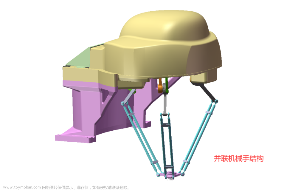
3-SPR并联机器人的运动学模型
S:球铰 P:移动副 R:转动副
3-SPR并联机器人即包含三条独立的SPR运动支链
输入:三个移动副(P)的伸长量
输出:系统末端参考点(一般是动平台的中心点)
运动学模型如下:
(这里的图使用了四个移动副,即在并联机构上串联了一个移动副,使其具有更大的运动范围)
对于3-SPR并联机器人来说,其末端参考点为
O
P
O_P
OP(动平台中心点)
对于串联移动副后的机构而言,其末端参考点为
O
T
O_T
OT(动平台上串联的移动副的末端)
| 符号 | 说明 |
|---|---|
| B 1 B_1 B1、 B 2 B_2 B2、 B 3 B_3 B3 | 球铰,三点的连线构成了静平台 |
| A 1 A_1 A1、 A 2 A_2 A2、 A 3 A_3 A3 | 转动副,三点的连线构成了动平台 |
| P 1 P_1 P1、 P 2 P_2 P2、 P 3 P_3 P3、 P 4 P_4 P4 | 移动副,并联机构的输入 |
逆运动学求解
3-SPR并联机器人的位置逆解可以描述为:当已知系统末端参考点 O P O_P OP在世界坐标系{W}下的坐标(即静平台所处的坐标系),求3-SPR并联机器人移动副 P 1 P_1 P1、 P 2 P_2 P2、 P 3 P_3 P3的伸长量。
求解公式:
公式的求解过程主要是利用约束条件,并联机器人在运动的过程中,其移动副
P
P
P的方向向量总是与转动副的旋转轴垂直的(
P
P
P的方向向量由球铰
B
B
B指向移动副中心点
A
A
A),建立三个约束方程,联立求解即可得到位置逆解(证明过程略,有人需要的话再放出)
由于球铰是非对称布置的,所以在求解时要将三个球铰的位置输入到公式中(
r
B
r_B
rB
1
_1
1、
r
B
r_B
rB
2
_2
2、
r
B
r_B
rB
3
_3
3)
方程注:变量说明见Matlab程序的注释
Matlab程序:
%***************************************************************
% ** Name:   非对称布置3-SPR并联机构的逆运动学求解                  **
% ** Author: __Lnx                                             **
% ** Date:   2023-03-26                                        **
% ** Input:  r1、r2、r3:球铰B1、B2、B3距离原点O_W的距离           **
%            X_a、Y_a、Z_a:代表末端参考点O_T要达到的位置           **
%            p4:移动副P4的伸长量,如是 3-SPR并联机构则将该值设定为0  **
%****************************************************************
function output = SPR_InverseKinematics(r1, r2, r3, X_a, Y_a, Z_a,p4)

    R_A = 78.603; % 动平台旋转副中心点外接圆半径(A1、A2、A3距离O_P的距离)
    syms Delt Theta Phi % 已知六个自由度中的三个,将剩下三个自由度设为要求的值

	% 旋转矩阵定义
    ux = cosd(Theta)*cosd(Delt);
    uy = cosd(Theta)*sind(Delt);
    uz = -sind(Theta);
    vx = sind(Phi)*sind(Theta)*cosd(Delt)-cosd(Phi)*sind(Delt);
    vy = sind(Phi)*sind(Theta)*sind(Delt)+cosd(Phi)*cosd(Delt);
    vz = sind(Phi)*cosd(Theta);
    wx = cosd(Phi)*sind(Theta)*cosd(Delt)+sind(Phi)*sind(Delt);
    wy = cosd(Phi)*sind(Theta)*sind(Delt)-sind(Phi)*cosd(Delt);
    wz = cosd(Phi)*cosd(Theta);
    R_l(1,1) = ux; R_l(1,2)=vx; R_l(1,3)=wx;
    R_l(2,1) = uy; R_l(2,2)=vy; R_l(2,3)=wy;
    R_l(3,1) = uz; R_l(3,2)=vz; R_l(3,3)=wz;

	% 由O_T的位置求出O_P的位置
    X_o = X_a-R_l(1,:)*[0 0 p4]';
    Y_o = Y_a-R_l(2,:)*[0 0 p4]';
    Z_o = Z_a-R_l(3,:)*[0 0 p4]';

	% 根据公式求解
    f1 = atand((3*(r2-r1)*(cosd(Theta)-cosd(Phi))+3*sqrt(3)*(r1+r2)*sind(Phi)*sind(Theta))/(4*sqrt(3)*r3*cosd(Theta)+3*(r2-r1)*sind(Phi)*sind(Theta)+sqrt(3)*(r1+r2)*(3*cosd(Phi)+cosd(Theta)))) == Delt;
    f2 = (6*(uz*vy-vz*uy)*Z_o-(3*(ux-vy)+sqrt(3)*(3*vx-uy))*uy*r2+2*(sqrt(3)*uy+3*vy)*uy*r3)/(6*(vx*uy-ux*vy)) == X_o;
    f3 = (6*(uz*vx-vz*ux)*Z_o-(3*(ux-vy)+sqrt(3)*(3*vx-uy))*ux*r2+2*(sqrt(3)*ux+3*vx)*uy*r3)/(6*(ux*vy-vx*uy)) == Y_o;

    [DELTA,THETA,PHI] = solve([f1, f2, f3],[Delt Theta Phi]);
    r = eval([DELTA,THETA,PHI]);

    T = r(2);D = r(1);P = r(3);
    rux = cosd(T)*cosd(D);
    ruy = cosd(T)*sind(D);
    ruz = -sind(T);
    rvx = sind(P)*sind(T)*cosd(D)-cosd(P)*sind(D);
    rvy = sind(P)*sind(T)*sind(D)+cosd(P)*cosd(D);
    rvz = sind(P)*cosd(T);
    rwx = cosd(P)*sind(T)*cosd(D)+sind(P)*sind(D);
    rwy = cosd(P)*sind(T)*sind(D)-sind(P)*cosd(D);
    rwz = cosd(P)*cosd(T);

    R(1,1) = rux; R(1,2)=rvx; R(1,3)=rwx;
    R(2,1) = ruy; R(2,2)=rvy; R(2,3)=rwy;
    R(3,1) = ruz; R(3,2)=rvz; R(3,3)=rwz;

    % 根据输入,计算球铰点坐标
    B1 = [r1*cosd(30) r1*sind(30) 0]';
    B2 = [r2*cosd(150)  r2*sind(150)  0]';
    B3 = [r3*cosd(270) r3*sind(270) 0]';

  	%根据求得的旋转矩阵,计算动平台中心点O_P的坐标
    O_A=[ X_a, Y_a, Z_a]';
    O_A = O_A-R*[0 0 p4]';

    % 根据求得的旋转矩阵及O_P点的坐标,计算各旋转副坐标
    A1 = R * [R_A*cosd(30) R_A*sind(30) 0]'+ O_A;
    A2 = R * [R_A*cosd(150)  R_A*sind(150)  0]'+ O_A;
    A3 = R * [R_A*cosd(270) R_A*sind(270) 0]'+ O_A;

    % 计算各杆伸长量
    P1 = norm(A1 - B1);
    P2 = norm(A2 - B2);
    P3 = norm(A3 - B3);

    % 输出结果
    r_output = [P1 P2 P3];
    output = r_output;
end
正运动学求解(待更新补充说明)
正运动学的求解和以往的方法不一样,利用了点云配准的思想。
主要思路是:


Matlab正运动学计算函数:SPR_ForwardKinematics文章来源:https://www.toymoban.com/news/detail-786727.html
%**********************************************************
% ** Name:   非对称布置3-SPR并联机构的正运动学求解            **
% ** Author: __Lnx                                       **
% ** Date:   2023-03-26                                  **
%**********************************************************
function [R_output,T_output] = SPR_ForwardKinematics(lidar1, lidar2, lidar3, p4)

%     这是一组示例
%     lidar1 = [304.455 1054.25 21.7591];
%     lidar2 = [302.484	1355.49	21.9924];
%     lidar3 = [297.842	1198	22.56111];
%     lidar1 = [304.455 711.704 29.55];
%     lidar2 = [302.484	1030.71	24.915];
%     lidar3 = [297.842	1030.71	24.915];
% 	  p4 = 500;

    % r 为球铰副距离世界坐标系原点距离;Spare_Local 为球铰副在动平台坐标系中的坐标
    [r,Spare_Local] = SPR_SpareJointCalculate(lidar1,lidar2,lidar3);
    Spare_World = [[r(1)*cosd(30) r(1)*sind(30) 0]' [r(2)*cosd(150)  r(2)*sind(150)  0]' [r(3)*cosd(270) r(3)*sind(270) 0]'];
    hold on;
%     scatter3(Spare_World(1,1),Spare_World(2,1),Spare_World(3,1));
%     scatter3(Spare_World(1,2),Spare_World(2,2),Spare_World(3,2));
%     scatter3(Spare_World(1,3),Spare_World(2,3),Spare_World(3,3));

    % ICP
    R = eye(3);      % 旋转矩阵初始化
    t = zeros(3, 1); % 位移矩阵初始化

    X = Spare_World; % 目标点云
    Y = Spare_Local; % 源点云

    % 计算Y中每个点到X中的最近点
    idx = [1 2 3]';
    err = norm(X(1)-Y(1))+norm(X(2)-Y(2))+norm(X(3)-Y(3));

    % 去中心
    Y_mean = mean(Y, 2);
    X_mean = mean(X(:, idx), 2);
    H = (Y - Y_mean) * (X(:, idx) - X_mean)';

    [U, ~, V] = svd(H);
    R_cur = V * U';
    t_cur = X_mean - R_cur * Y_mean;

    % 更新变换矩阵
    R = R_cur;
    t = R_cur * t + t_cur;


    % 更新点云
    Y = R_cur * Y + t_cur;
    hold on;
    scatter3(Y(1,:),Y(2,:),Y(3,:),'red');
    scatter3(X(1,:),X(2,:),X(3,:),'black');
axis equal;
    R_output = R;
    T_output = t + R*[0,0,p4]';
end
其中包含另一个函数:SPR_SpareJointCalculate(lidar1,lidar2,lidar3)文章来源地址https://www.toymoban.com/news/detail-786727.html
%**********************************************************
% ** Name:   三个球铰的位置计算                             **
% ** Author: __Lnx                                       **
% ** Date:   2023-03-16                                  **
%**********************************************************


function [output_r,output_B] = SPR_SpareJointCalculate(lidar1,lidar2,lidar3)
    % 输入
    theta =[lidar1(3) lidar2(3) lidar3(3)];
    P =[lidar1(2) lidar2(2) lidar3(2)];
    % 常量
    alpha = [30 150 270];
    r = 78.603; % 动平台转动副外切圆半径
    k = 42.5;

    l = 139.135;
    m = 159.966;%220;
    P = P + l + m;  % 移动副长度

    alpha = deg2rad(alpha);
    theta = deg2rad(theta);

    % 计算B1\B2\B3在动平台坐标系中的位置
    B1 = [(r+P(1)*sin(theta(1))-k*cos(theta(1)))*cos(alpha(1))
          (r+P(1)*sin(theta(1))-k*cos(theta(1)))*sin(alpha(1))
           -(P(1)*cos(theta(1))+k*sin(theta(1)))];
    B2 = [(r+P(2)*sin(theta(2))-k*cos(theta(2)))*cos(alpha(2))
          (r+P(2)*sin(theta(2))-k*cos(theta(2)))*sin(alpha(2))
           -(P(2)*cos(theta(2))+k*sin(theta(2)))];
    B3 = [(r+P(3)*sin(theta(3))-k*cos(theta(3)))*cos(alpha(3))
          (r+P(3)*sin(theta(3))-k*cos(theta(3)))*sin(alpha(3))
           -(P(3)*cos(theta(3))+k*sin(theta(3)))];
    hold on;
%     scatter3(B1(1),B1(2),B1(3));
%     scatter3(B2(1),B2(2),B2(3));
%     scatter3(B3(1),B3(2),B3(3));
%     output_B = [B2 B3 B1];% 非对称
      output_B = [B1 B2 B3];% 对称

    L(1) = norm(B1-B2);
    L(2) = norm(B1-B3);
    L(3) = norm(B2-B3);

    syms r1 r2 r3;
    f1 = r2^2+r3^2+r2*r3 == L(1)^2;
    f2 = r1^2+r3^2+r1*r3 == L(2)^2;
    f3 = r1^2+r2^2+r1*r2 == L(3)^2;
    [r1,r2,r3] = solve([f1, f2, f3],[r1 r2 r3]);
%     r = eval([r2 r1 r3]);% 非对称
    r = eval([r1 r2 r3]);% 对称

    for i=1:1:size(r,1) % 正数解
        if(r(i,1)>0 && r(i,2)>0 && r(i,3)>0)
            output_r = r(i,:);
            break;
        end
    end
end
到了这里,关于非对称3-SPR并联机器人正逆运动学(Matlab源码)的文章就介绍完了。如果您还想了解更多内容,请在右上角搜索TOY模板网以前的文章或继续浏览下面的相关文章,希望大家以后多多支持TOY模板网!


