目录
1,NVIC
2,中断和事件的区别
3,优先级的概念
4,如何实际编程使用外部中断
5,STM32开发板通过按键控制LED
5.1,打开相应GPIO模块时钟
5.2,NVIC设置
5.3,外部中断线和配套的GPIO进行连接映射
5.4,代码文件
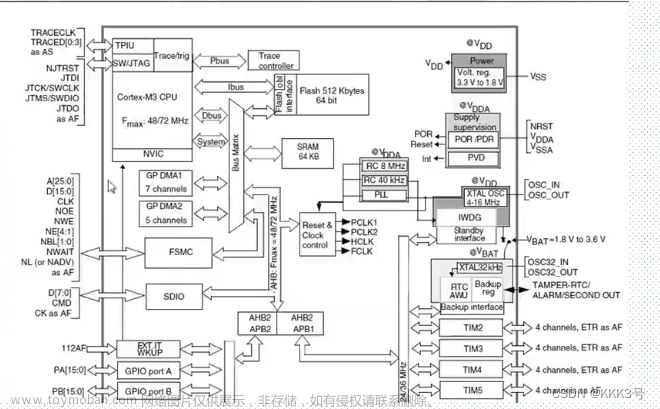
6,FSMC
1,NVIC
NVIC: Nested Vector Interrupt Control,嵌套向量中断控制器;
68个可屏蔽中断通道。

数据手册得向量表结合起始代码查看:
可以理解为数组里(__Vectors )定义了数据类型为DCD的许多个元素。

下边图中可理解为复位时调用Reset_Handler函数,先执行SystemInit,然后执行__main:

本章节我们关注的是外部中断相关的内容:

起始代码中为我们提供了中断函数默认的执行程序,即下图中的 B . ,其含义即是C中的while(1)。

起始文件中的这些函数属性是[WEAK],即弱函数。
始代码文件是用汇编语言编写,[WEAK]标志代表该函数是弱函数,如果在其它地方定义这些函数则以定义的函数执行,也就是不再执行默认的while(1)函数,如果没有在其它地方定义则以起始文件中的函数为准。
起始代码的作用可以认为是建立了中断向量表,中断向量表是软件实现的,但是是由硬件决定的。
即下图中的地址是硬件设计时就决定了的。

中断要配置使能,中断处理程序要清中断挂起。
2,中断和事件的区别

中断需要CPU参与,事件不需要CPU参与,中断使用CPU处理程序比较灵活,事件不需要CPU参与通过产生脉冲直接与外设交互,可以节省CPU资源。
3,优先级的概念
抢占优先级 NVIC_IRQChannelPreemptionPriority
子优先级 NVIC_IRQChannelSubPriority
级别的数字越小,优先级越高。
抢占优先级内部划分子优先级,同一抢占优先级内的中断子优先级必须不同。
优先级为0的抢占优先级可以打断优先级为1的抢占优先级。
同一抢占优先级内等级为0的子优先级中断不能打断等级为1的子优先级中断,只有两个不同子优先级的中断同时发生时,子优先级高的中断才会处于优先地位。

4,如何实际编程使用外部中断
(1)时钟设置并打开相应GPIO模块时钟
(2)将相应GPIO配置为浮空输入
(3)NVIC设置
(4)将外部中断线和配套的GPIO进行连接映射
(5)外部中断线使能触发
(6)准备好ISR,并在ISR处等待执行中断程序即可
在下一节中通过相应的代码对应对上述步骤。
5,STM32开发板通过按键控制LED
中断相关标准库代码在misc.c中,misc是miscellaneous(杂项)的缩写。
在51单片机中已经通过使用中断,通过识别外部按键操作来控制LED灯。本节在STM32开发板上,通过使用标准库中的中断函数来控制LED灯,达到的效果为:按一个按键打开LED灯,按另一个按键关闭这个LED灯,主程序中控制另外一个LED灯闪烁。
5.1,打开相应GPIO模块时钟
本例中按键使用PIN角为PB8和PB9连接按键,所以要使能GPIOB端口所在的APB2总线时钟,LED灯使用PA0和PA。
对应的标准库函数是stm32f10x_rcc.c文件中的RCC_APB2PeriphClockCmd(),要使能该总线时钟,对应的命令如下:
RCC_APB2PeriphClockCmd(RCC_APB2Periph_GPIOB, ENABLE);

RCC_APB2PeriphClockCmd(RCC_APB2Periph_GPIOA, ENABLE);
5.2,NVIC设置
第一步,优先级组设置,设置有几个抢占优先级,以及有几个子优先级
对于抢占优先级和子优先级,因为本例中通过按键控制LED灯只需要识别一个中断,因此抢占优先级和子优先级可以随意设置,即NVIC_PriorityGroupConfig()函数的输入参数可以设置下列代码中的任意值,对于具体的项目可以根据中断个数和优先级进行设置。
/**
  * @brief  Configures the priority grouping: pre-emption priority and subpriority.
  * @param  NVIC_PriorityGroup: specifies the priority grouping bits length.
  *   This parameter can be one of the following values:
  *     @arg NVIC_PriorityGroup_0: 0 bits for pre-emption priority
  *                                4 bits for subpriority
  *     @arg NVIC_PriorityGroup_1: 1 bits for pre-emption priority
  *                                3 bits for subpriority
  *     @arg NVIC_PriorityGroup_2: 2 bits for pre-emption priority
  *                                2 bits for subpriority
  *     @arg NVIC_PriorityGroup_3: 3 bits for pre-emption priority
  *                                1 bits for subpriority
  *     @arg NVIC_PriorityGroup_4: 4 bits for pre-emption priority
  *                                0 bits for subpriority
  * @retval None
  */
void NVIC_PriorityGroupConfig(uint32_t NVIC_PriorityGroup)
{
  /* Check the parameters */
  assert_param(IS_NVIC_PRIORITY_GROUP(NVIC_PriorityGroup));

  /* Set the PRIGROUP[10:8] bits according to NVIC_PriorityGroup value */
  SCB->AIRCR = AIRCR_VECTKEY_MASK | NVIC_PriorityGroup;
}
第二步,NVIC初始化
标准库misc.c中的NVIC_Init()函数
/**
  * @brief  Initializes the NVIC peripheral according to the specified
  *         parameters in the NVIC_InitStruct.
  * @param  NVIC_InitStruct: pointer to a NVIC_InitTypeDef structure that contains
  *         the configuration information for the specified NVIC peripheral.
  * @retval None
  */
void NVIC_Init(NVIC_InitTypeDef* NVIC_InitStruct)
{
  uint32_t tmppriority = 0x00, tmppre = 0x00, tmpsub = 0x0F;

  /* Check the parameters */
  assert_param(IS_FUNCTIONAL_STATE(NVIC_InitStruct->NVIC_IRQChannelCmd));
  assert_param(IS_NVIC_PREEMPTION_PRIORITY(NVIC_InitStruct->NVIC_IRQChannelPreemptionPriority));
  assert_param(IS_NVIC_SUB_PRIORITY(NVIC_InitStruct->NVIC_IRQChannelSubPriority));

  if (NVIC_InitStruct->NVIC_IRQChannelCmd != DISABLE)
  {
    /* Compute the Corresponding IRQ Priority --------------------------------*/
    tmppriority = (0x700 - ((SCB->AIRCR) & (uint32_t)0x700))>> 0x08;
    tmppre = (0x4 - tmppriority);
    tmpsub = tmpsub >> tmppriority;

    tmppriority = (uint32_t)NVIC_InitStruct->NVIC_IRQChannelPreemptionPriority << tmppre;
    tmppriority |=  NVIC_InitStruct->NVIC_IRQChannelSubPriority & tmpsub;
    tmppriority = tmppriority << 0x04;

    NVIC->IP[NVIC_InitStruct->NVIC_IRQChannel] = tmppriority;

    /* Enable the Selected IRQ Channels --------------------------------------*/
    NVIC->ISER[NVIC_InitStruct->NVIC_IRQChannel >> 0x05] =
      (uint32_t)0x01 << (NVIC_InitStruct->NVIC_IRQChannel & (uint8_t)0x1F);
  }
  else
  {
    /* Disable the Selected IRQ Channels -------------------------------------*/
    NVIC->ICER[NVIC_InitStruct->NVIC_IRQChannel >> 0x05] =
      (uint32_t)0x01 << (NVIC_InitStruct->NVIC_IRQChannel & (uint8_t)0x1F);
  }
}
5.3,外部中断线和配套的GPIO进行连接映射
首先,确定按键和LED对应的PIN端口。通用I/O端口以下图的方式连接到16个外部中断/事件线上,若按键确定连接到PA0上,则对应的中断线为EXTI0。

在外部中断配置寄存器(AFIO_EXTICRX,X = 1,2,3,4)中设置中断线与哪个PIN角对应。
对应的设置函数是标准库GPIO.c文件中的GPIO_EXTILineConfig()函数:
/**
  * @brief  Selects the GPIO pin used as EXTI Line.
  * @param  GPIO_PortSource: selects the GPIO port to be used as source for EXTI lines.
  *   This parameter can be GPIO_PortSourceGPIOx where x can be (A..G).
  * @param  GPIO_PinSource: specifies the EXTI line to be configured.
  *   This parameter can be GPIO_PinSourcex where x can be (0..15).
  * @retval None
  */
void GPIO_EXTILineConfig(uint8_t GPIO_PortSource, uint8_t GPIO_PinSource)
{
  uint32_t tmp = 0x00;
  /* Check the parameters */
  assert_param(IS_GPIO_EXTI_PORT_SOURCE(GPIO_PortSource));
  assert_param(IS_GPIO_PIN_SOURCE(GPIO_PinSource));

  tmp = ((uint32_t)0x0F) << (0x04 * (GPIO_PinSource & (uint8_t)0x03));
  AFIO->EXTICR[GPIO_PinSource >> 0x02] &= ~tmp;
  AFIO->EXTICR[GPIO_PinSource >> 0x02] |= (((uint32_t)GPIO_PortSource) << (0x04 * (GPIO_PinSource & (uint8_t)0x03)));
}
如果要设置PIN角PA0能够检测中断,调用此函数:
GPIO_EXTILineConfig(GPIO_PortSourceGPIOA,GPIO_PinSource0);确定模式是中断还是事件;
typedef enum
{
  EXTI_Mode_Interrupt = 0x00,
  EXTI_Mode_Event = 0x04
}EXTIMode_TypeDef;
配置上升沿/下降沿触发选择寄存器;
因开发板上的按键接通时是接地的,因此需要将中断设置为下降沿触发,设置下降沿触发选择寄存器(EXTI_FTSR)

对应的标准库中代码:
typedef enum
{
  EXTI_Trigger_Rising = 0x08,
  EXTI_Trigger_Falling = 0x0C,
  EXTI_Trigger_Rising_Falling = 0x10
}EXTITrigger_TypeDef;
重写中断函数ISR:
注意中断函数的名称要使用起始代码中的对应中断函数名称,也就是对这个弱函数重写。
注意要在ISR中清除中断挂起寄存器(EXTI_PR),如果不在ISR中清除中断就会反复进入中断:

对应的标准库函数在stm32f10x_exti.c中的EXTI_ClearFlag(),
/**
  * @brief  Clears the EXTI's line pending flags.
  * @param  EXTI_Line: specifies the EXTI lines flags to clear.
  *   This parameter can be any combination of EXTI_Linex where x can be (0..19).
  * @retval None
  */
void EXTI_ClearFlag(uint32_t EXTI_Line)
{
  /* Check the parameters */
  assert_param(IS_EXTI_LINE(EXTI_Line));

  EXTI->PR = EXTI_Line;
}
5.4,代码文件
中断相关.c和.h文件:
#ifndef _exti_H
#define _exti_H


#include "system.h"

void My_EXTI_Init(void);

#endif
注意:需将AFIO使能,因为中断线和端口的对应配置是在AFIO相关寄存器:外部中断配置寄存器(AFIO_EXTICR)

#include "exti.h"
#include "led.h"
#include "SysTick.h"
#include "key.h"


void My_EXTI_Init(void)
{
	NVIC_InitTypeDef NVIC_InitStructure;
	EXTI_InitTypeDef  EXTI_InitStructure;

	RCC_APB2PeriphClockCmd(RCC_APB2Periph_AFIO,ENABLE);  //注意需将AFIO使能

	GPIO_EXTILineConfig(GPIO_PortSourceGPIOB, GPIO_PinSource8);
	GPIO_EXTILineConfig(GPIO_PortSourceGPIOB, GPIO_PinSource9);

	NVIC_PriorityGroupConfig(NVIC_PriorityGroup_2);
	NVIC_InitStructure.NVIC_IRQChannel = EXTI9_5_IRQn;
	NVIC_InitStructure.NVIC_IRQChannelPreemptionPriority=2;
	NVIC_InitStructure.NVIC_IRQChannelSubPriority =3;
	NVIC_InitStructure.NVIC_IRQChannelCmd = ENABLE;
	NVIC_Init(&NVIC_InitStructure);


	EXTI_InitStructure.EXTI_Line=EXTI_Line8|EXTI_Line9;
	EXTI_InitStructure.EXTI_Mode=EXTI_Mode_Interrupt;
	EXTI_InitStructure.EXTI_Trigger=EXTI_Trigger_Falling;
	EXTI_InitStructure.EXTI_LineCmd=ENABLE;
	EXTI_Init(&EXTI_InitStructure);

}


void EXTI9_5_IRQHandler(void)
{
	if(EXTI_GetITStatus(EXTI_Line8)==1)
	{
		delay_ms(10);
		if(KEY1==0)
		{
			led2=0;
		}
	}
	else if(EXTI_GetITStatus(EXTI_Line9)==1)
	{
		delay_ms(10);
		if(KEY2==0)
		{
			led2=1;
		}
	}
	EXTI_ClearITPendingBit(EXTI_Line8|EXTI_Line9);
}main.c函数:文章来源:https://www.toymoban.com/news/detail-799577.html
#include "system.h"
#include "SysTick.h"
#include "led.h"
#include "key.h"
#include "exti.h"

int main()
{
	u8 i;
	SysTick_Init(72);

	LED_Init();
	KEY_Init();
	My_EXTI_Init();
	while(1)
	{
		i++;
		if(i%20==0)
		{
			led1=!led1;
		}
		delay_ms(10);
	}
}
6,FSMC
Flexible static memory controller(FSMC)灵活的静态存储控制器文章来源地址https://www.toymoban.com/news/detail-799577.html
到了这里,关于单片机第三季-第七课:STM32中断体系的文章就介绍完了。如果您还想了解更多内容,请在右上角搜索TOY模板网以前的文章或继续浏览下面的相关文章,希望大家以后多多支持TOY模板网!

