一、实验题目:
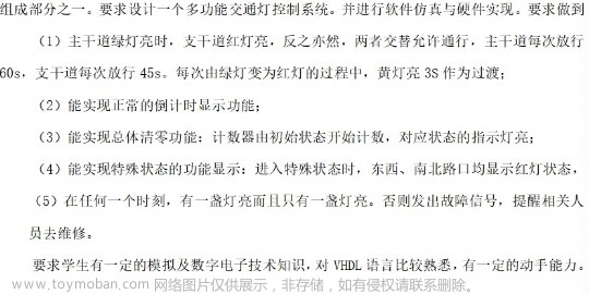
结合高云MiniStar_Nano EDA开发板,完成设计十字路口交通信号灯控制系统。
1.要求该交通灯为三色灯控制器,红灯亮表示禁止通行,绿灯亮表示允许通行,黄灯亮表示要求压线车辆快速穿越。主干道和次干道灯的亮灭时序按照交通规则设置。
2.可以调整主干道和次干道绿灯和红灯亮的时间(必须是两位数)。
3.能用倒计时显示时间。
4.具有红绿灯手动控制功能。
二、实验原理:
此处使用开发板上的三色灯充当交通灯的显示。由于开发板上接口数量不太充足,因此仅使用两组三色灯以演示主干道和辅道的交通灯的亮灭顺序。
首先是交通灯的显示逻辑。此处共有四种显示状态:主干道红灯辅道绿灯;主干道红灯辅道黄灯;主干道绿灯辅道红灯以及主干道黄灯辅道红灯。交通灯会沿着这些状态依次点亮并在上述四种状态中不断循环。
其次是数码管显示逻辑。此处仅有四位数码管,正好匹配两组三色灯的显示,当交通灯处在某一状态中,需要实时倒计时显示当前状态的剩余时长,故需要匹配计时与数码管显示的内容。
最后是其他的一些模块。如数码管位选模块,倒计时模块和分频模块,由于这些模块在之前的实验中已经使用过,故不在此进行说明,而在下方代码中进行一定说明。
三、实验方案:
下方为模块介绍:
freq_div:分频模块,对开发板的时钟脉冲进行分频,产生所需的时钟信号。此处需要产生1s的时钟脉冲,则分频比应与开发板的时钟频率一致。
`timescale 1ns/1ns

module freq_div#(
    parameter DIV_RATE_2N = 11
)(
    input   clk_in_i,
    input   rst_i,
    output  reg clk_out_o
);

    localparam SIM_DELAY = 1;
    localparam CNT_WIDTH = $clog2(DIV_RATE_2N);

    reg [CNT_WIDTH-1:0] counter;
    always  @(posedge clk_in_i or posedge rst_i) begin
        if(rst_i) begin//高电平置零
            counter     <= #SIM_DELAY 0;
            clk_out_o   <= #SIM_DELAY 0;
        end else begin //低电平计数器加一
            if(counter < DIV_RATE_2N/2-1) begin
                counter     <= #SIM_DELAY counter + 1;
            end else begin //完成一轮计数后置零进行循环计数
                counter     <= #SIM_DELAY 0;
                clk_out_o   <= #SIM_DELAY ~clk_out_o;
            end
        end
    end
endmodule
mux_4x4:位选模块,判断当前显示为哪一位数码管,与seg_ctrl模块和shift_reg模块组合实现数码管显示逻辑
`timescale 1ns/1ns

module mux_4x4(
    input       [3:0]   index_i,
    input       [15:0]   data_i,
    output  reg [3:0]   data_o
);

    always@(*) begin
        case(index_i[3:0])
        4'b0001:data_o = data_i[3:0];
        4'b0010:data_o = data_i[7:4];
        4'b0100:data_o = data_i[11:8];
        4'b1000:data_o = data_i[15:12];
        default:data_o = 4'h0;
        endcase
   end

endmodule
seg_ctrl:数码管控制模块,实例化mux_4x4模块与shift_reg模块,实现数码管显示逻辑
`timescale 1ns/1ns

module seg_ctrl #(
    parameter DIG_WIDTH = 4
)(
    input                   clk,
    input                   rst,
    input [DIG_WIDTH*4-1:0] data_i,
    output[DIG_WIDTH-1:0]   dig_o,
    output[7:0]             seg_o
);

    localparam CLK_IN_FREQ = 27000000;

    wire clk_100Hz;

    freq_div #(
        .DIV_RATE_2N (200000)
    )freq_div_i(
        .clk_in_i   (clk),
        .rst_i      (rst),
        .clk_out_o  (clk_100Hz)
    );

    shift_reg #(
        .WIDTH      (4),
        .INIT_VALUE (4'h1)
    )shift_reg_i(
        .clk        (clk_100Hz),
        .rst        (rst),
        .load_i     (1'b0),
        .load_data_i(4'h0),
        .reg_in_i   (dig_o[3]),
        .reg_out_o  (dig_o[3:0])
    );

    wire [3:0]data_sel;
    mux_4x4 mux_4x4_i(
        .index_i    (dig_o[3:0]),
        .data_i     (data_i[15:0]),
        .data_o     (data_sel[3:0])
    );
    seg_decode seg_decode_i(
        .data_i     (data_sel[3:0]),
        .seg_code_o (seg_o[7:0])
);
endmodule
shift_reg:移位模块,随着mux_4x4模块的移动实现不同数字的显示。与seg_ctrl模块,mux_4x4模块组合实现数码管显示逻辑。
`timescale 1ns/1ns

module shift_reg #(
    parameter DIRECTION = "LEFT",
    parameter WIDTH     = 9,
    parameter INIT_VALUE= 9'h1
)(
    input                  clk,
    input                  rst,
    input                  load_i,
    input       [WIDTH-1:0]load_data_i,
    input                  reg_in_i,
    output  reg [WIDTH-1:0]reg_out_o
);

    localparam SIM_DELAY = 1;

    always @(posedge clk or posedge rst or posedge load_i) begin
        if(rst) begin //时钟信号复位
            reg_out_o <= #SIM_DELAY INIT_VALUE;
        end else if(load_i) begin //对reg_out_o赋初值,但此处并未使用该方法赋值,而是在下方的else语句中赋值
            reg_out_o <= #SIM_DELAY load_data_i;
            end else begin
                reg_out_o <= #SIM_DELAY DIRECTION=="LEFT"?//左移
                        {reg_out_o[WIDTH-2:0],reg_in_i}:
                        {reg_in_i,reg_out_o[WIDTH-1:1]};
        end
    end

endmodule
seg_decode:译码模块,将送入的信号进行译码,实现数码管显示对应的数字。
module seg_decode #(
    parameter INVERSE = 1'b1
)(
    input   [3:0] data_i,
    output  [7:0] seg_code_o
);
    reg [7:0] seg_code;

    assign seg_code_o[7:0] = INVERSE ?~seg_code[7:0] : seg_code[7:0];

        always @(*) begin
            case(data_i[3:0])
            4'h0:   seg_code = 8'h3f;
            4'h1:   seg_code = 8'h06;
            4'h2:   seg_code = 8'h5b;
            4'h3:   seg_code = 8'h4f;
            4'h4:   seg_code = 8'h66;
            4'h5:   seg_code = 8'h6d;
            4'h6:   seg_code = 8'h7d;
            4'h7:   seg_code = 8'h07;
            4'h8:   seg_code = 8'h7f;
            4'h9:   seg_code = 8'h6f;
            default:seg_code = 8'h00;
            endcase
        end
endmodule
sub_counter:自减器模块,基于循环主体产生自减信号,如此处循环分为四个部分,总时长为66s,故产生自66开始自减的计数信号
`timescale 1ns/1ns

module sub_counter#(
    parameter WIDTH    = 8,
    parameter DATA_MAX = 256
)(
    input                clk,
    input                rst,
    input           [1:0]button,
    output reg           cout_o,
    output reg [WIDTH-1:0]count_o
);

    localparam SIM_DELAY = 1;

    always @(posedge clk or posedge rst) begin
        if(rst) begin
            cout_o      <=#SIM_DELAY 0;
            count_o     <=#SIM_DELAY DATA_MAX;
        end else if(count_o >0) begin
                cout_o      <=#SIM_DELAY 1'b0;
                count_o     <=#SIM_DELAY count_o - 1;
            end else begin
                cout_o      <=#SIM_DELAY 1'b1;
                count_o     <=#SIM_DELAY DATA_MAX;
        end
    end
endmodule
time_all:控制显示时间的状态机模块,通过总循环的自减信号来判断当前状态的时长,并进行状态跳转。
`timescale 1ns/1ns

module time_all(
    input      [7:0]time_all,
    input           clk,
    input           rst,
    output reg[15:0]a
);
always@(posedge rst or posedge clk)begin
    if(rst)begin
        a[3:0]      <=0;//主道个位
        a[7:4]      <=0;//主道十位
        a[11:8]     <=0;//辅道个位
        a[15:12]    <=0;//辅道十位
    end
    else if(time_all>33)begin//主道红灯,辅道绿灯
        a[3:0]      <=(time_all+3-33)%10;
        a[7:4]      <=(time_all+3-33)/10;
        a[11:8]     <=(time_all-33)%10;
        a[15:12]    <=(time_all-33)/10;
    end
    else if((time_all>30)&&(time_all<33))begin//主道红灯,辅道黄灯
        a[3:0]      <=(time_all+3-33)%10;
        a[7:4]      <=(time_all+3-33)/10;
        a[11:8]     <=(time_all-30)%10;
        a[15:12]    <=0;
    end
    else if((time_all>3)&&(time_all<30))begin//主道绿灯,辅道红灯
        a[3:0]      <=(time_all-3)%10;
        a[7:4]      <=(time_all-3)/10;
        a[11:8]     <=(time_all)%10;
        a[15:12]    <=(time_all)/10;
    end
    else if((time_all>0)&&(time_all<3))begin//主道黄灯,辅道红灯
        a[3:0]      <=(time_all)%10;
        a[7:4]      <=(time_all)/10;
        a[11:8]     <=(time_all)%10;
        a[15:12]    <=0;
    end
end
endmodule
traffic_led_demo:主函数模块,通过例化模块完成交通灯功能。
`timescale 1ns/1ns

module traffic_led_demo(
    input             clk,
    input           rst_n,
    input     [1:0]button,
    output     [3:0]dig_o,
    output     [7:0]seg_o,
    output     [5:0]led_o
);

    localparam CLK_FREQ_Hz=27000000;
    wire rst=~rst_n;
    wire clk_out_o;
    wire [7:0]time_all;
    wire[15:0]a;
    wire [1:0]c;
    freq_div#(
        .DIV_RATE_2N(27000000)
    )freq_div_i(
        .clk_in_i   (clk),
        .rst_i      (rst),
        .clk_out_o  (clk_out_o)
    );
    sub_counter#(
        .WIDTH      (8),
        .DATA_MAX   (60)
    )sub_counter_i(
         .button     (button[1:0]),
         .clk        (clk_out_o),
         .rst        (rst),
         .cout_o     (),
         .count_o    (time_all[7:0])
    );
    time_all time_all_i(
        .time_all   (time_all[7:0]),
        .clk        (clk_out_o),
        .rst        (rst),
        .a          (a)
);
    state_ctrl state_ctrl_i(
        .clk        (clk),
        .rst        (rst),
        .time_all   (time_all[7:0]),
        .led_o      (led_o[5:0])
);
    seg_ctrl#(
        .DIG_WIDTH  (4)
    )seg_ctrl_i(
        .clk        (clk),
        .rst        (rst),
        .data_i     (a[15:0]),
        .dig_o      (dig_o[3:0]),
        .seg_o      (seg_o[7:0])
);
endmodule
state_ctrl:控制led灯点亮状态的状态机模块,通过总循环的自减信号来判断当前状态的点亮的led灯,注意此处led灯点亮信号为0信号而不是1信号。
`timescale 1ns/1ns

module state_ctrl(
    input            clk,
    input            rst,
    input  [7:0]time_all,
    output reg[5:0]led_o
);
    parameter ST0 =2'h0;
    parameter ST1 =2'h1;
    parameter ST2 =2'h2;
    parameter ST3 =2'h3;

    reg [1:0]curr_state;

    always@(posedge clk or posedge rst)
        if(rst)
             curr_state<=ST0;
        else  //灯的顺序为红黄绿
            case(curr_state)
            ST0:begin
            if(time_all>33)begin//主道红灯,辅道绿灯
                led_o<=6'b011110;
                curr_state<=ST0;
            end else begin
                curr_state<=ST1;
            end
        end
            ST1:begin
            if((time_all>30)&&(time_all<33))begin//主道红灯,辅道黄灯
                led_o<=6'b011101;
                curr_state<=ST1;
            end else begin
                curr_state<=ST2;
            end
        end
            ST2:begin
            if((time_all>3)&&(time_all<30))begin//主道绿灯,辅道红灯
                led_o<=6'b110011;
                curr_state<=ST2;
            end else begin
                curr_state<=ST3;
            end
        end
            ST3:begin
            if((time_all>0)&&(time_all<3))begin//主道黄灯,辅道红灯
                led_o<=6'b101011;
                curr_state<=ST3;
            end else begin
                curr_state<=ST0;
            end
        end
     endcase
endmodule
四、实验结果:
下方为实验结果截图,此处由于三色灯中没有黄灯,故使用蓝灯代替共工实现了功能一和功能三


五、调试中遇到的问题:
首先遇到的问题便是三色LED灯不受控制的点亮,该问题是由于三色LED灯的点亮是0信号而不是1信号,在修改完对应的显示逻辑后,进而实现了可控点亮。
其次是数码管显示时会持续显示某一个数字而不发生变化,这是由于模块在实例化时所输入的时钟信号不匹配导致部分模块实例化时出现问题,进而出现数码管显示问题。在修改输入时钟信号后交通灯正常运行
最后是交通灯逻辑问题。每当交通灯完成第四个状态时重新回到第一个状态时,数码管显示的数字并非对应的式子,而是总时长的倒计时显示。这是由于状态机显示模块的第四个模块对应的状态的逻辑判定中有一定问题,在增加了限制条件后得以消除该现象
六、优化思路:
在time_all模块中增加常量a初值为60,并在逻辑中将判定值修改为a的倍数,同时在顶层模块中的time_all实例化中增加常量初始化,之后就可以通过修改总时长来修改交通灯中每个灯点亮的时长,提高模块的适用性。
如果要进一步提高适用性,可以重新写一个模块,将交通灯循环的初值赋予放在模块中,并增加按钮输入实现按一下加一秒或减一秒,进而实现功能二文章来源:https://www.toymoban.com/news/detail-805480.html
对于功能四,可以在time_all的判定中增加两个判定条件,当按钮按下时将状态转移到两个状态的起始状态,但实际编写时发现这样会导致数码管显示出现问题,会卡在某个状态而且不跳转。初步判断是因为状态判断时的逻辑不正确,检测按钮状态应该是先按下在抬起的逻辑,即判断对应端口由低电平跳转到高电平在跳转到低电平,只有这样才可以完成红绿灯的功能三。文章来源地址https://www.toymoban.com/news/detail-805480.html
到了这里,关于基于高云FPGA开发板的十字路口交通灯的文章就介绍完了。如果您还想了解更多内容,请在右上角搜索TOY模板网以前的文章或继续浏览下面的相关文章,希望大家以后多多支持TOY模板网!


