一、ESP8266模块
1.模块介绍
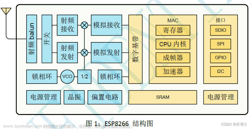
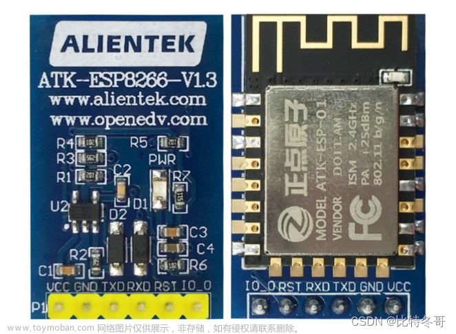
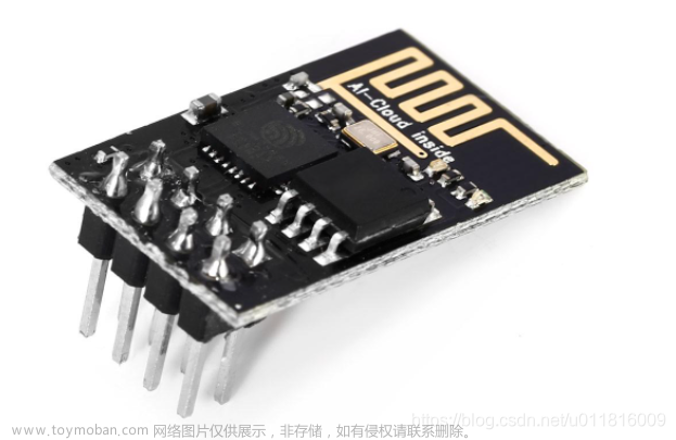
本项目无线通讯模块使用的是WiFi模块ESP8266,乐鑫公司推出的高性能、低功耗串口WiFi模块ESP8266应该是使用最广泛的一种WIFI模块之一了,它自身带有高性能的MCU(Microcontroller Unit),因此它既可以通过串口连接为外部MCU提供 WiFi通信功能,也就是我们本项目所用到的功能;当然它也可以让用户直接在模块内置的MCU上基于RTOS SDK进行软件编程,开发出具有低功耗、低成本的WiFi连接产品,如市面上大部分WiFi智能插座就用了ESP8266模块和它的这一功能。
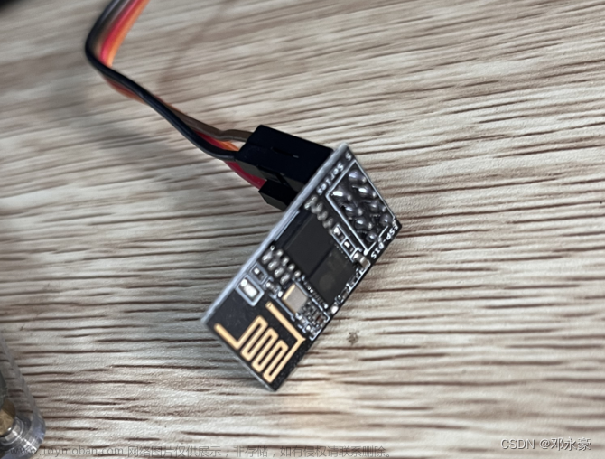
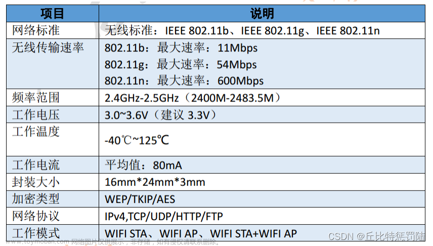
ESP8266内置一个Tensilica(泰思立达)Xtensa架构的32位处理器L106,具有5级流水线(ARM CortexM3是3级流水线),最大时钟速度为160MHz,可以使用高达16MB的外部SPI Flash。该模块采用串口与MCU(或其他串口设备)通信,内置 TCP/IP协议栈,能够实现串口与 WiFi之间的转换。通过该模块,传统的串口设备只需要简单的串口配置,即可通过WiFi传输自己的数据。
WiFi具有两种功能模式:一种叫AP(Access Point)模式,一种叫Station模式。AP就是我们平时所说的热点,如无线路由器,开了热点的手机等,这些AP设备可以允许其他设备(如手机,PC等)输入热点名(SSID)和密码(也可不设置密码)后连接上网;Station模式则是前面说的连接AP的设备(如手机,PC等)。
ESP8266除支持上述两种模式以外,还可以支持第三种模式:AP+Station,即:将AP和Station的功能合二为一,它主要是实现无线桥接的功能,该模式应用的场景不多。
STM32单片机在与ESP8266进行串口通信时采用AT命令进行通信,这样想要做ESP8266 WiFi模块的程序开发的话,那我们首先得学习并熟练掌握ESP8266 WiFi模块的AT指令。
2.AT指令介绍
AT指令是以AT作为开头,\r\n字符结束的字符串,每个指令执行成功与否都有相应的返回。其他的一些非预期的信息(如有人拨号进来、线路无信号等),模块将有对应的一些信息提示,接收端可做相应的处理。
不同模块的AT命令可能不一样的,这要对着模块的AT指令手册来查看。
AT命令可分为四类:
| 类型 | 指令格式 | 描述 |
|---|---|---|
| 执行指令 | AT+ | 该命令用于执行受模块内部程序控制的变参数不可变的功能。 |
| 测试指令 | AT+=? | 该命令用于该命令用于查询设置指令的参数以及取值范围。 |
| 查询指令 | AT+? | 该命令用于返回参数的当前值。 |
| 设置指令 | AT+=<···> | 该命令用于设置用户自定义的参数值。 |
2.硬件连接
由于我的开发板当中3.3V电源是LDO电路从USB TypeC接口提供的5V降压而来,电流较低,所以连ESP8266模块可能会导致它不能正常工作,所以这里我连了5V做VCC,而我所用的ESP8266能够正常工作,具体所用的时候可以视情况而定。
提示:USB3.0的接口电流较高,如果必要用5V,最好不用USB3.0
ESP8266模块提供TTL串口通信接口,而我所使用的开发板上的扩展UART2串口也是TTL电平,所以直接连接如下:

二、串口转发及调试
1.串口转发流程
开发板的USART2串口连接了ESP8266模块,当然我们要通过PC来对它进行调试,所以我们需要STM32写一个单片机上写一个串口接收转发的程序如下图:
2.串口转发程序实现
STM32CubeMX配置

修改usart.h/.c文件
对usart.h文件做如下修改:
... ...
/* USER CODE BEGIN Private defines */
extern char g_uart1_rxbuf[256];
extern uint8_t g_uart1_bytes;


#define clear_uart1_rxbuf() do { memset(g_uart1_rxbuf, 0, sizeof(g_uart1_rxbuf)); \
		g_uart1_bytes=0; } while(0)

//在这里添加uar2接收 buffer相关变量声明,并添加一个宏 clear_uart2_rxbuf()用来清除接收 buffer里的数据
extern char g_uart2_rxbuf[256];
extern uint8_t g_uart2_bytes;


#define clear_uart2_rxbuf() do { memset(g_uart2_rxbuf, 0, sizeof(g_uart2_rxbuf)); \
		g_uart2_bytes=0; } while(0)

//添加串口接收转发函数的声明
extern void uart_forward(void);

/* USER CODE END Private defines */
... ...
对usart.c文件做如下修改:
... ...
/* USER CODE BEGIN 0 */
static	uint8_t			s_uart1_rxch;
char					g_uart1_rxbuf[256];
uint8_t					g_uart1_bytes;

static	uint8_t			s_uart2_rxch;
char					g_uart2_rxbuf[256];
uint8_t					g_uart2_bytes;
/* USER CODE END 0 */
... ...

void MX_USART2_UART_Init(void)
{
... ...
  /* USER CODE BEGIN USART2_Init 2 */
  HAL_UART_Receive_IT(&huart2 , &s_uart2_rxch, 1);//HAL_UART_Receive_IT中断服务处理程序
  /* USER CODE END USART2_Init 2 */

}
... ...

/* USER CODE BEGIN 1 */
void HAL_UART_RxCpltCallback(UART_HandleTypeDef *huart)
{
	if (huart->Instance == USART1)
	{
		if( g_uart1_bytes< sizeof(g_uart1_rxbuf) )
		{
			g_uart1_rxbuf[g_uart1_bytes++] = s_uart1_rxch;
		}
		HAL_UART_Receive_IT(&huart1 , &s_uart1_rxch, 1);
	}

	if (huart->Instance == USART2)
		{
			if( g_uart2_bytes< sizeof(g_uart2_rxbuf) )
			{
				g_uart2_rxbuf[g_uart2_bytes++] = s_uart2_rxch;
			}
			HAL_UART_Receive_IT(&huart2 , &s_uart2_rxch, 1);
		}
}

//添加usart1和usart2的收发转发功能函数,main()函数中调用
void uart_forward(void)
{
	if(strstr(g_uart1_rxbuf, "\r\n"))
	{
		HAL_UART_Transmit(&huart2, (uint8_t *)g_uart1_rxbuf, g_uart1_bytes,0xFF);
		clear_uart1_rxbuf();
	}

	if(g_uart2_bytes > 0)
	{
		HAL_Delay(100);/*Wait AT command reply receive over*/
		HAL_UART_Transmit(&huart1, (uint8_t *)g_uart2_rxbuf, g_uart2_bytes,0xFF);
		clear_uart2_rxbuf();
	}
}
... ...

/* USER CODE END 1 */

... ...
修改main.c文件
如下:
... ...
  while(1)
  {
	  uart_forward();//后面使用无线通讯时只需要用Socket通信,不在需要此转发程序,如果没有注释掉会报错,并不会执行PC发的JOSN指令
#if 0
... ...
#endif
    /* USER CODE END WHILE */

    /* USER CODE BEGIN 3 */
    }... ...
3.运行测试
用串口调试工具进行测试:
三、AT指令学习
每一个使用AT指令通信的模块都有自己详细的AT指令使用说明文档,模块里的软件固件版本不一样,其AT指令可能也不大一样,可以通过你的模块以及版本找到对应的说明文档对照。
对于我所使用的ESP8266 WiFi模块:
1.WiFi初始化命令
| AT命令 | 说明 |
|---|---|
| AT | AT命令用来确认模块是否正常工作以及串口通信是否正常 |
| AT+GMR | 获取WiFi模块的软件固件版本信息 |
| AT+RST | 重启、复位WiFi模块 |
| AT+CWMODE_CUR=1 | 设置ESP8266 WiFi模块工作在Station模式 |
| AT+CWDHCP_CUR=1,1 | 设置使能ESP8266 WiFi模块Station模式的DHCP服务 |
| AT+CIPSTA_CUR | 静态设置ESP8266的IP地址,子网掩码和默认网关 |
2.无线连接命令
| AT命令 | 说明 |
|---|---|
| AT+CWJAP_CUR=“Router_SSID” ,“Password” | 该命令用来连接指定的无线路由器 |
| AT+CIPSTA_CUR? | 该命令用来查看ESP8266当前的IP地址 |
| AT+PING=“192.168.0.1” | 该命令用来测试与目标主机的连通性 |
3.数据收发命令
| AT命令 | 说明 |
|---|---|
| AT+CIPMUX=0 | 该命令用来禁用多个socket连接,一般只连接一个目标服务器。 |
| AT+CIPSTART=“TCP”,“192.168.0.100"”,12345 | 该命令用来连接指定的目标socket 服务器 |
| AT+CIPSEND=5 | 该命令用来发送5个字节的数据,在收到模块回应的‘>’字符后,开始输入要发送的数据内容。 |
| AT+CIPCLOSE | 该命令用来断开Socket连接 |
注意:指令带_CUR后缀则表示只更改当前系统配置,并不写入Flash存储器中,重启复位后失效。而如果需要重启后依然有效则用带_DEF后缀的命令。
四、WiFi模块实时上报温湿度与远程控制LED灯实现
1.esp8266.h/.c
代码如下:
/*
 * esp8266.h
 *
 *  Created on: 2023年2月26日
 *      Author: ASUS
 */

#ifndef INC_ESP8266_H_
#define INC_ESP8266_H_

#include <stdio.h>

#define wifi_huart			&huart2			/*wiFi模块使用的串口*/
#define g_wifi_rxbuf		g_uart2_rxbuf	/*wiFi模块的接收buffer */
#define g_wifi_rxbytes		g_uart2_bytes 	/*wiFi模块接收的数据大小*/

/*清除WiFi模块接收 buffer里的数据内容宏,用宏不用函数是因为函数调用需要额外时间开销*/
#define clear_atcmd_buf()	do { memset(g_wifi_rxbuf, 0, sizeof(g_wifi_rxbuf));g_wifi_rxbytes=0; } while(0)

/*ESP8266 WiFi模块发送AT命令函数,返回值为О表示成功,!0表示失败*/
#define EXPECT_OK	"OK\r\n"
extern int send_atcmd(char *atcmd, char *expect_reply, unsigned int timeout);

/*ESP8266 WiFi模块初始化函数。返回值为0表示成功,!0表示失败*/
extern int esp8266_module_init(void);

/*ESP8266 WiFi模块复位重启函数。返回值为О表示成功,!0表示失败*/
extern int esp8266_module_reset(void);

/*ESP8266 WiFi模块连接路由器函数。返回值为О表示成功,!0表示失败*/
extern int esp8266_join_network( char *ssid,char *pwd) ;

/*ESP8266获取自己的IP地址和网关IP地址。返回值为О表示成功,!O表示失败*/
int esp8266_get_ipaddr(char *ipaddr, char *gateway, int ipaddr_size);

/*ESP8266 WiFi模块做ping 命令测试网络连通性。返回值为О表示成功,!0表示失败*/
int esp8266_ping_test(char *host);

/*ESP8266 WiFi模块建立TCP socket连接函数。返回值为О表示成功,!0表示失败*/
extern int esp8266_sock_connect( char *servip, int port);

/* ESP8266 WiFi模块断开TCP socket连接函数。返回值为О表示成功,!0表示失败*/
extern int esp8266_sock_disconnect(void);

/*ESP8266 WiFi通过 TCP Socket发送数据函数。返回值为0表示失败,>0表示成功发送字节数*/
extern int esp8266_sock_send(unsigned char *data, int bytes);

/* ESP8266 WiFi通过TCP Socket 接收数据函数。返回值为0无数据,>0表示接收到数据字节数*/
extern int esp8266_sock_recv(unsigned char *buf, int size);

#endif /* INC_ESP8266_H_ */
/*
 * esp8266.c
 *
 *  Created on: 2023年2月26日
 *      Author: ASUS
 */

#include <stdlib.h>
#include "usart.h"
#include "esp8266.h"

/*WiFi模块驱动调试宏,注释下面两个宏定义可以取消调试打印*/
//#define CONFIG_WIFI_DEBUG
#define CONFIG_WIFI_PRINT

#ifdef CONFIG_WIFI_DEBUG
#define wifi_dbg(format,args...) printf(format, ##args)
#else
#define wifi_dbg(format,args...) do{} while(0)
#endif

#ifdef CONFIG_WIFI_PRINT
#define wifi_print(format,args...) printf(format, ##args)
#else
#define wifi_print(format,args...) do{} while(0)
#endif

int send_atcmd(char *atcmd, char *expect_reply, unsigned int timeout)
{
	int				rv = 1;
	unsigned int	i;
	char			*expect;

	/*check function input arguments validation*/
	if( !atcmd || strlen(atcmd)<=0 )
	{
		wifi_print("ERROR:Invalid input arguments\r\n");
		return -1;
	}

	wifi_dbg("\r\nStart send AT command: %s",atcmd);
	clear_atcmd_buf();
	HAL_UART_Transmit(wifi_huart, (uint8_t *)atcmd, strlen(atcmd), 1000);

	expect = expect_reply ? expect_reply : "OK\r\n";

	/*Receive AT reply string by UART interrupt handler,stop by "OK/ERROR" or timeout*/
	for(i=0; i<timeout; i++)
	{
		if( strstr(g_wifi_rxbuf, expect))
		{
			wifi_dbg("AT command Got expect reply '%s'\r\n", expect);
			rv = 0;
			goto CleanUp;
		}
		if( strstr(g_wifi_rxbuf, "ERROR\r\n") || strstr(g_wifi_rxbuf, "FAIL\r\n"))
		{
			rv = 2;
			goto CleanUp;
		}

		HAL_Delay(1);
	}


CleanUp:
	wifi_dbg("<<<< AT command reply:\r\n%s", g_wifi_rxbuf);
	return rv;

}

int atcmd_send_data(unsigned char *data, int bytes, unsigned int timeout)
{
	int				rv = -1;
	unsigned int	i;

	/* check function input arguments validation */
	if( !data || bytes <= 0 )
	{
		wifi_print("ERROR: Invalid input arguments\r\n");
		return -1;
	}

	wifi_dbg("\r\nStart AT command send [%d] bytes data\n", bytes);
	clear_atcmd_buf();
	HAL_UART_Transmit(wifi_huart, data, bytes, 1000);

	/*Receive AT reply string by UART interrupt handler,stop by "OK/ERROR" or timeout */
	for(i=0; i<timeout; i++)
	{
		if(strstr(g_wifi_rxbuf, "SEND OK\r\n"))
		{
			rv = 0;
			goto CleanUp;
		}
		if(strstr(g_wifi_rxbuf, "ERROR\r\n"))
		{
			rv = 1;
			goto CleanUp;
		}

		HAL_Delay(1);
	}


CleanUp:
	wifi_dbg("<<<< AT command reply:\r\n%s", g_wifi_rxbuf);
	return rv;
}

int esp8266_module_init(void)
{
	int		i;

	wifi_print("INFO: Reset ESP8266 module now...\r\n");
	send_atcmd("AT+RST\r\n", EXPECT_OK, 500);

	for(i=0; i<6; i++)
	{
		if( !send_atcmd("AT\r\n", EXPECT_OK, 500) )
		{
			wifi_print("INFO: Send AT to ESP8266 and got reply ok \r\n");
			break;
		}

		HAL_Delay(100);
	}

	if( i>= 6 )
	{
		wifi_print("ERROR: Can't receive AT replay after reset\r\n");
		return -2;
	}

	if( send_atcmd( "AT+CWMODE=1\r\n", EXPECT_OK, 500) )
	{
		wifi_print("ERROR : Set ESP8266 work as station mode failure\r\n");
		return -3;
	}

	if( send_atcmd("AT+CWDHCP=1,1\r\n", EXPECT_OK, 500) )
	{
		wifi_print("ERROR: Enable ESP8266 Station mode DHCP failure\r\n");
		return -4;
	}

#if 0
	if( send_atcmd( "AT+GMR\r\n",EXPECT_OK,500))
	{
		wifi_print("ERROR: AT+GMR check ESP8266 reversion failure\r\n");
		return -5;
	}
#endif
	HAL_Delay(500);
	return 0;
}


int esp8266_join_network(char *ssid, char *pwd)
{
	char			atcmd[128] = {0x00};
	int				i;

	if( !ssid || !pwd )
	{
		wifi_print( "ERROR:Invalid input arguments\r\n");
		return -1;
	}

	snprintf(atcmd, sizeof(atcmd), "AT+CWJAP=\"%s\",\"%s\"\r\n", ssid, pwd);
	if( send_atcmd(atcmd, "CONNECTED", 10000) )
	{
		wifi_print("ERROR: ESP8266 connect to '%s' failure\r\n", ssid);
		return -2 ;
	}
	wifi_print("INFO: ESP8266 connect to '%s' ok\r\n", ssid);

	/*check got IP address or not by netmask (255.)*/
	for(i=0; i<10; i++)
	{
		if( !send_atcmd( "AT+CIPSTA_CUR?\r\n", "255.", 1000))
		{
			wifi_print( "INFO: ESP8266 got Ip address ok\r\n" );
			return 0;
		}

		HAL_Delay(300);
	}

	wifi_print("ERROR: ESP8266 assigned IP address failure\r\n");
	return -3;
}

/*
+CIPSTA_CUR:ip: "192.168.0.120"
+CIPSTA_CUR:gateway: "192.168.0.1"
*/
static int util_parser_ipaddr(char *buf, char *key, char *ipaddr, int size)
{
	char		*start;
	char		*end;
	int			len;

	if(!buf || !key || !ipaddr)
	{
		return -1;
	}
	/*find the key string */
	start = strstr(buf, key);
	if( !start )
	{
		return -2;
	}

	start+=strlen(key) + 1;/*Skip ”*/
	end = strchr(start,'"');/*find last " */
	if( !end )
	{
		return -3;
	}

	len = end - start;
	len = len>size ? size : len;

	memset(ipaddr, 0, size);
	strncpy(ipaddr, start, len);

	return 0;
}

int esp8266_get_ipaddr(char *ipaddr, char *gateway, int ipaddr_size)
{
	if( !ipaddr || !gateway || ipaddr_size<7 )
	{
		wifi_print("ERROR: Invalid input arguments\r\n");
		return -1;
	}

	if( send_atcmd( "AT+CIPSTA_CUR?\r\n", "255.", 1000) )
	{
		wifi_print("ERROR: ESP8266 AT+CIPSTA_CUR? command failure\r\n");
		return -2;
	}

	if( util_parser_ipaddr(g_wifi_rxbuf, "ip:", ipaddr, ipaddr_size) )
	{
		wifi_print("ERROR: ESP8266 AT+CIPSTA_CUR? parser IP address failure\r\n");
		return -3;
	}

	if( util_parser_ipaddr(g_wifi_rxbuf, "gateway:", gateway, ipaddr_size))
	{
		wifi_print("ERROR: ESP8266 AT+CIPSTA_CUR? parser gateway failure\r\n");
		return -4;
	}

	wifi_print("INFO: ESP8266 got IP address[%s] gateway[%s] ok\r\n", ipaddr, gateway);
	return 0;
}

int esp8266_ping_test(char *host)
{
	char			atcmd[128]={0x00};

	if(!host)
	{
		wifi_print( "ERROR: Invalid input arguments\r\n" );
		return -1;
	}

	snprintf(atcmd, sizeof(atcmd), "AT+PING=\"%s\"\r\n", host);
	if( send_atcmd( atcmd, EXPECT_OK, 3000) )
	{
		wifi_print("ERROR: ESP8266 ping test [%s ] failure\rin", host);
		return -2;
	}

	wifi_print("INFO: ESP8266 ping test [%s ] ok\r\n", host);
	return 0;
}

int esp8266_sock_connect(char *servip, int port)
{
	char			atcmd[128] = {0x00};

	if( !servip || port<=0 )
	{
		wifi_print("ERROR: Invalid input arguments\rin");
		return -1;
	}

	send_atcmd ( "AT+CIPMUX=0\r\n", EXPECT_OK, 1500);

	snprintf(atcmd, sizeof(atcmd), "AT+CIPSTART=\"TCP\",\"%s\",%d\r\n", servip, port);
	if(send_atcmd(atcmd,"CONNECT\r\n", 1000) )
	{
		wifi_print("ERROR: ESP8266 socket connect to [%s:%d] failure\r\n", servip, port);
		return -2;
	}

	wifi_print("INFO: ESP8266 socket connect to [%s:%d] ok\r\n", servip, port);
	return 0;
}

int esp8266_sock_disconnect(void)
{
	send_atcmd("AT+CIPCLOSE\r\n", EXPECT_OK, 1500);
	return 0;
}

int esp8266_sock_send(unsigned char *data, int bytes)
{
	char			atcmd[128] = {0x00};

	if( !data || bytes<=0)
	{
		wifi_print("ERROR: Invalid input arguments\r\n");
		return -1;
	}

	snprintf(atcmd, sizeof(atcmd),  "AT+CIPSEND=%d\r\n", bytes);
	if( send_atcmd(atcmd, ">", 500))
	{
		wifi_print("ERROR: AT+CIPSEND command failure\rin");
		return 0;
	}

	if( atcmd_send_data((unsigned char *)data, bytes, 1000))
	{
		wifi_print("ERROR: AT+CIPSEND send data failure\r\n");
		return 0;
	}

	return bytes;
}

int esp8266_sock_recv( unsigned char *buf, int size)
{
	char			*data = NULL;
	char			*ptr = NULL;

	int				len;
	int				rv;
	int				bytes;

	if( !buf || size <= 0)
	{
		wifi_print("ERROR: Invalid input arguments\r\n");
		return -1;
	}

	if( g_wifi_rxbytes <= 0 )
	{
		return 0;
	}

	/*No data arrive or not integrated */
	if( !(ptr=strstr(g_wifi_rxbuf, "+IPD,")) || !(data=strstr( ptr, ":")) )
	{
		return 0;
	}

	data++;
	bytes = atoi(ptr+strlen("+IPD,"));

	len = g_wifi_rxbytes - (data-g_uart2_rxbuf);

	if( len < bytes )
	{
		wifi_dbg("+IPD data not receive over, receive again later ...\r\n");
		return 0;
	}

	memset(buf, 0, size);
	rv = bytes>size ? size : bytes;
	memcpy(buf, data, rv);

	clear_atcmd_buf();

	return rv;
}
2.main.c
代码如下:
/* USER CODE BEGIN Header */
/**
******************************************************************************
* @file : main.c
* @brief : Main program body
******************************************************************************
* @attention
*
* <h2><center>© Copyright (c) 2022 STMicroelectronics.
* All rights reserved.</center></h2>
*
* This software component is licensed by ST under BSD 3-Clause license,
* the "License"; You may not use this file except in compliance with the
* License. You may obtain a copy of the License at:
* opensource.org/licenses/BSD-3-Clause
*
******************************************************************************
*/
/* USER CODE END Header */
/* Includes ------------------------------------------------------------------*/
#include "main.h"
#include "adc.h"
#include "tim.h"
#include "usart.h"
#include "gpio.h"
/* Private includes ----------------------------------------------------------*/
/* USER CODE BEGIN Includes */
#include <string.h>
#include <stdio.h>
#include "dht11.h"
#include "sht30.h"
#include "core_json.h"
#include "oled.h"
#include "esp8266.h"
/* USER CODE END Includes */
/* Private typedef -----------------------------------------------------------*/
/* USER CODE BEGIN PTD */
/* USER CODE END PTD */
/* Private define ------------------------------------------------------------*/
/* USER CODE BEGIN PD */
/* USER CODE END PD */
/* Private macro -------------------------------------------------------------*/
/* USER CODE BEGIN PM */
/* USER CODE END PM */
/* Private variables ---------------------------------------------------------*/
/* USER CODE BEGIN PV */
#define FLAG_WIFI_CONNECTED (1<<0) /* WiFi连接路由器标志位*/
#define FLAG_SOCK_CONNECTED (1<<1) /* Socket连接服务器标志位*/
/* USER CODE END PV */
/* Private function prototypes -----------------------------------------------*/
void SystemClock_Config(void);
/* USER CODE BEGIN PFP */
/* USER CODE END PFP */
/* Private user code ---------------------------------------------------------*/
/* USER CODE BEGIN 0 */
static int report_tempRH_json(void);
static int parser_led_json(char *json_string, int bytes);
static void proc_uart1_recv(void);
/* USER CODE END 0 */
/**
* @brief The application entry point.
* @retval int
*/
int main(void)
{
/* USER CODE BEGIN 1 */
// uint32_t lux,noisy;
// uint32_t start = 0;
// uint32_t light_status = 0;
// float temperature, humidity;
uint32_t last_time = 0; /*每隔3s上报一次,上一次上报的时间*/
unsigned char buf[256]; /*WiFi模块socket接收的buffer */
int rv;
char ipaddr[16];
char gateway[16];
unsigned char wifi_flag = 0;
/* USER CODE END 1 */
/* MCU Configuration--------------------------------------------------------*/
/* Reset of all peripherals, Initializes the Flash interface and the Systick. */
HAL_Init();
/* USER CODE BEGIN Init */
/* USER CODE END Init */
/* Configure the system clock */
SystemClock_Config();
/* USER CODE BEGIN SysInit */
/* USER CODE END SysInit */
/* Initialize all configured peripherals */
MX_GPIO_Init();
MX_TIM6_Init();
MX_USART1_UART_Init();
MX_ADC1_Init();
MX_USART2_UART_Init();
/* USER CODE BEGIN 2 */
/* USER CODE END 2 */
/* Infinite loop */
/* USER CODE BEGIN WHILE */
//sysled_hearbeat();
//beep_start(3,300);
printf("Start BearKE1 5G NB_IoT Board Example Program v1.0\r\n");
printf("Welcome Mr.deng!\r\n");
OLED_Init();
OLED_ShowBanner(TIME_1S*2);
esp8266_module_init();
while(1)
{
/*wiFi没有连接上无线路由器的话,开始连接无线路由器并ping测试*/
if(!(wifi_flag&FLAG_WIFI_CONNECTED))
{
if(esp8266_join_network("SSID", "password"))//填写自己的WiFi信息
{
esp8266_module_init();
HAL_Delay(2000);
continue;
}
if(esp8266_get_ipaddr(ipaddr, gateway, sizeof(ipaddr)))
{
HAL_Delay(1000);
continue;
}
if(esp8266_ping_test(gateway))
{
HAL_Delay(1000);
continue;
}
wifi_flag |= FLAG_WIFI_CONNECTED; /* set wifi connected flag */
}
/*网络socket没有连接上Socket服务器的话就开始连接Socket服务器 */
if(!(wifi_flag&FLAG_SOCK_CONNECTED))
{
if(esp8266_sock_connect("192.168.0.120", 12345))//修改为自己对应的IP与端口
{
HAL_Delay(1000);
continue;
}
wifi_flag |= FLAG_SOCK_CONNECTED; /* set wifi connected flag */
}
/*接收并且打印Socket服务器发送过来的数据*/
// rv = esp8266_sock_recv(buf, sizeof(buf));
// printf(("%d\n"), rv);
if( (rv=esp8266_sock_recv(buf, sizeof(buf))) > 0 )
{
parser_led_json((char *)buf, rv);
printf("ESP8266 socket receive %d bytes data: %s\n", rv, buf);
}
/*定时发数据到Socket服务器*/
if(time_after(HAL_GetTick(), last_time+3000))
{
rv = report_tempRH_json();
if( rv == 0 )
{
printf("ESP8266 socket send message ok\n");
}
else
{
printf("ESP8266 socket send message failure, rv=%d\n", rv);
wifi_flag &= ~FLAG_SOCK_CONNECTED;/* clear socket connected flag */
if(esp8266_ping_test(gateway))
{
wifi_flag &= ~FLAG_WIFI_CONNECTED;/* clear wifi connected flag */
}
}
last_time = HAL_GetTick();/*update last report time */
}
// uart_forward();//后面使用无线通讯时只需要用Socket通信,不在需要此转发程序,如果没有注释掉会报错,并不会执行PC发的JOSN指令
#if 0
/*sht30*/
report_tempRH_json();
HAL_Delay(3000);
/*json上报*/
proc_uart1_recv();
if( report_tempRH_json() < 0 )
{
printf("ERROR: UART report temperature and relative humidity failure\r\n");
}
HAL_Delay(3000);
// if( DHT11_SampleData(&temperature, &humidity) < 0 )
// {
// printf("ERROR: DHT11 Sample Data failure\r\n");
// }
// else
// {
// printf("DHT11 Sample Temperature: %.3f Relative Humidity: %.3f\r\n", temperature, humidity);
// }
//
//
// HAL_Delay(1000);
//Tag:灯光
// if( OFF == light_status )
// {
// adc_sample_lux_noisy(&lux, &noisy);
// printf("Lux[%lu] Noisy[%lu]\r\n", lux, noisy);
// if( lux<400 && noisy>800 )
// {
// printf("Turn Light on\r\n");
// turn_relay(Relay2,ON);
// turn_led(GreenLed,ON);//还得写turn_Led()
// light_status = ON;
//
// start = HAL_GetTick();
// }
HAL_Delay(5000);
// }
//
// else
// {
// if( time_after(HAL_GetTick(), start+15000) )
// {
// printf("Turn Light off\r\n");
// turn_relay(Relay2,OFF);
// turn_led(GreenLed,OFF);
// turn_led(RedLed,ON);
//
// HAL_Delay(1000);
// turn_led(RedLed,OFF);
//
// light_status = OFF;
// }
//
// }
//
// HAL_Delay(10);
#endif
/* USER CODE END WHILE */
/* USER CODE BEGIN 3 */
}
/* USER CODE END 3 */
}
/**
* @brief System Clock Configuration
* @retval None
*/
void SystemClock_Config(void)
{
RCC_OscInitTypeDef RCC_OscInitStruct = {0};
RCC_ClkInitTypeDef RCC_ClkInitStruct = {0};
RCC_PeriphCLKInitTypeDef PeriphClkInit = {0};
/** Initializes the RCC Oscillators according to the specified parameters
* in the RCC_OscInitTypeDef structure.
*/
RCC_OscInitStruct.OscillatorType = RCC_OSCILLATORTYPE_HSE;
RCC_OscInitStruct.HSEState = RCC_HSE_ON;
RCC_OscInitStruct.PLL.PLLState = RCC_PLL_ON;
RCC_OscInitStruct.PLL.PLLSource = RCC_PLLSOURCE_HSE;
RCC_OscInitStruct.PLL.PLLM = 1;
RCC_OscInitStruct.PLL.PLLN = 20;
RCC_OscInitStruct.PLL.PLLP = RCC_PLLP_DIV7;
RCC_OscInitStruct.PLL.PLLQ = RCC_PLLQ_DIV2;
RCC_OscInitStruct.PLL.PLLR = RCC_PLLR_DIV2;
if (HAL_RCC_OscConfig(&RCC_OscInitStruct) != HAL_OK)
{
Error_Handler();
}
/** Initializes the CPU, AHB and APB buses clocks
*/
RCC_ClkInitStruct.ClockType = RCC_CLOCKTYPE_HCLK|RCC_CLOCKTYPE_SYSCLK
|RCC_CLOCKTYPE_PCLK1|RCC_CLOCKTYPE_PCLK2;
RCC_ClkInitStruct.SYSCLKSource = RCC_SYSCLKSOURCE_PLLCLK;
RCC_ClkInitStruct.AHBCLKDivider = RCC_SYSCLK_DIV1;
RCC_ClkInitStruct.APB1CLKDivider = RCC_HCLK_DIV1;
RCC_ClkInitStruct.APB2CLKDivider = RCC_HCLK_DIV1;
if (HAL_RCC_ClockConfig(&RCC_ClkInitStruct, FLASH_LATENCY_4) != HAL_OK)
{
Error_Handler();
}
PeriphClkInit.PeriphClockSelection = RCC_PERIPHCLK_USART1|RCC_PERIPHCLK_USART2
|RCC_PERIPHCLK_ADC;
PeriphClkInit.Usart1ClockSelection = RCC_USART1CLKSOURCE_PCLK2;
PeriphClkInit.Usart2ClockSelection = RCC_USART2CLKSOURCE_PCLK1;
PeriphClkInit.AdcClockSelection = RCC_ADCCLKSOURCE_PLLSAI1;
PeriphClkInit.PLLSAI1.PLLSAI1Source = RCC_PLLSOURCE_HSE;
PeriphClkInit.PLLSAI1.PLLSAI1M = 1;
PeriphClkInit.PLLSAI1.PLLSAI1N = 9;
PeriphClkInit.PLLSAI1.PLLSAI1P = RCC_PLLP_DIV7;
PeriphClkInit.PLLSAI1.PLLSAI1Q = RCC_PLLQ_DIV2;
PeriphClkInit.PLLSAI1.PLLSAI1R = RCC_PLLR_DIV6;
PeriphClkInit.PLLSAI1.PLLSAI1ClockOut = RCC_PLLSAI1_ADC1CLK;
if (HAL_RCCEx_PeriphCLKConfig(&PeriphClkInit) != HAL_OK)
{
Error_Handler();
}
/** Configure the main internal regulator output voltage
*/
if (HAL_PWREx_ControlVoltageScaling(PWR_REGULATOR_VOLTAGE_SCALE1) != HAL_OK)
{
Error_Handler();
}
}
/* USER CODE BEGIN 4 */
int parser_led_json(char *json_string, int bytes)
{
JSONStatus_t result;
char save;
char *value;
size_t valen;
int i;
printf("DBUG: Start parser JSON string: %s\r\n", json_string);
result = JSON_Validate(json_string, bytes);
/* JSON document is valid so far but incomplete */
if( JSONPartial == result )
{
printf("WARN: JSON document is valid so far but incomplete!\r\n");
return 0;
}
/* JSON document is not valid JSON */
if( JSONSuccess != result )
{
printf("ERROR: JSON document is not valid JSON!\r\n");
return -1;
}
/* Parser and set LED status */
for(i=0; i<LedMax; i++)
{
result = JSON_Search( json_string, bytes, leds[i].name, strlen(leds[i].name), &value, &valen);
if( JSONSuccess == result )
{
save = value[valen];
value[valen] = '\0';
if( !strncasecmp(value, "on", 2) )
{
printf("DBUG: turn %s on\r\n", leds[i].name);
turn_led(i, ON);
}
else if( !strncasecmp(value, "off", 3) )
{
printf("DBUG: turn %s off\r\n", leds[i].name);
turn_led(i, OFF);
}
value[valen] = save;
}
}
return 1;
}
void proc_uart1_recv(void)
{
if( g_uart1_bytes > 0 )
{
HAL_Delay(200);
if( 0 != parser_led_json(g_uart1_rxbuf, g_uart1_bytes) )
{
clear_uart1_rxbuf();
}
}
}
/*json上报*/
//int report_tempRH_json(void)
//{
// char buf[128];
// float temperature, humidity;
//
//
// if ( DHT11_SampleData(&temperature, &humidity) < 0 )
// {
// printf("ERROR: DHT11 Sample data failure\n");
// return -1;
// }
//
//
// memset(buf, 0, sizeof(buf));
// snprintf(buf, sizeof(buf), "{\"Temperature\":\"%.2f\", \"Humidity\":\"%.2f\"}", temperature, humidity);
//
// HAL_UART_Transmit(&huart1 , (uint8_t *)buf, strlen(buf), 0xFFFF);
//
// return 0;
//}
/*sht30采样*/
int report_tempRH_json(void)
{
char buf[128];
float temperature, humidity;
uint32_t temp, humd;
int rv;
if ( SHT30_SampleData(&temperature, &humidity) < 0 )
{
printf("ERROR: SHT30 Sample data failure\n");
return -1;
}
memset(buf, 0, sizeof(buf));
snprintf(buf, sizeof(buf), "{\"Temperature\":\"%.2f\", \"Humidity\":\"%.2f\"}", temperature, humidity);
temp = (int)(temperature*100);
humd = (int)(humidity*100);
OLED_ShowTempHumdity(temp, humd, TIME_1S*2);
rv = esp8266_sock_send((uint8_t *)buf, strlen(buf));
// HAL_UART_Transmit(&huart1 , (uint8_t *)buf, strlen(buf), 0xFFFF);
return rv>0 ? 0 : -2;
}
/* USER CODE END 4 */
/**
* @brief This function is executed in case of error occurrence.
* @retval None
*/
void Error_Handler(void)
{
/* USER CODE BEGIN Error_Handler_Debug */
/* User can add his own implementation to report the HAL error return state */
__disable_irq();
while (1)
{
}
/* USER CODE END Error_Handler_Debug */
}
#ifdef USE_FULL_ASSERT
/**
* @brief Reports the name of the source file and the source line number
* where the assert_param error has occurred.
* @param file: pointer to the source file name
* @param line: assert_param error line source number
* @retval None
*/
void assert_failed(uint8_t *file, uint32_t line)
{
/* USER CODE BEGIN 6 */
/* User can add his own implementation to report the file name and line number,
ex: printf("Wrong parameters value: file %s on line %d\r\n", file, line) */
/* USER CODE END 6 */
}
#endif /* USE_FULL_ASSERT */
/************************ (C) COPYRIGHT STMicroelectronics *****END OF FILE****/
注意:需要注释掉转发程序,不然无法控制Led灯
3.运行测试


总结
首先,对于STM32单片机在写博客之前学习了,所以没有,之后可能也会对之前的内容整理为博客,包括Led、DHT11、SHT30、I2C协议、SPI协议及JSON格式远程控制等,所以之前内容并未包括在此篇当中。
本篇为ESP8266 WiFi模块实时上报温湿度及控制LED灯项目笔记,主要介绍和应用了ESP8266 WiFi模块,编写了串口转发程序,学习了AT命令等,最终实现了ESP8266 WiFi模块实时上报温湿度及控制LED灯项目。文章来源:https://www.toymoban.com/news/detail-811587.html
别忘了点赞 关注 收藏呀!文章来源地址https://www.toymoban.com/news/detail-811587.html
到了这里,关于【STM32】ESP8266 WiFi模块实时上报温湿度及控制LED灯项目笔记的文章就介绍完了。如果您还想了解更多内容,请在右上角搜索TOY模板网以前的文章或继续浏览下面的相关文章,希望大家以后多多支持TOY模板网!


