一、IIC简介
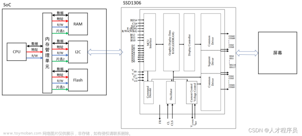
如图所示,IIC总线由SDA数据线和SCL时钟线组成,同时总线上外接上拉电阻确保信号的稳定性,设备对应挂载到总线上。
1.1 IIC总线频率
IIC总线时钟频率经过两次分频可得,如下图所示。
时钟频率的计算公式如下:
- I2C模块时钟(I2C Module Clock) = 系统时钟(SYSCLK) / (I2CPSC + 1)
- I2C总线时钟(I2C Master Clock) = I2C模块时钟(I2C Module Clock) / (ICCL + d) + (ICCH + d)
为了满足所有I2C协议时序规范,I2C模块时钟必须在7-12MHz之间。

其中d的取值取决于I2CPSC寄存器位IPSC的值,如下图所示:
IPSC = 0, d = 7; IPSC = 1, d = 6; IPSC > 1, d = 5.

I2CPSC寄存器的IPSC位介绍:

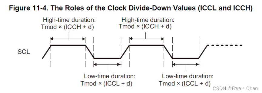
从下图可以看到IIC总线的时钟频率,当IIC模块时钟频率(Tmod)固定时,ICCH和ICCL设置的值越大,对应SCL总线上高低电平占比越长,因此SCL(IIC总线上)的时钟频率越小,对IIC设备的读取速度越慢。
二、寄存器说明
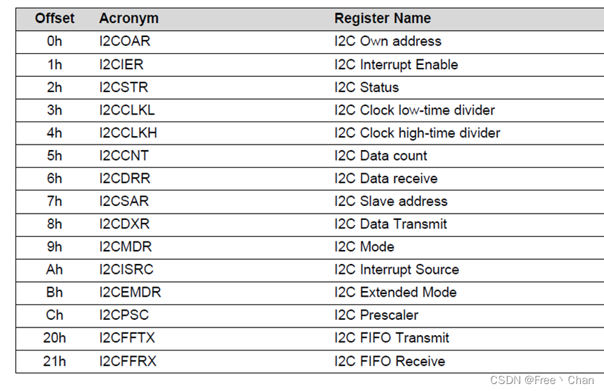
2.1 相关寄存器概览
2.2 I2COAR
设置I2C自身地址(主机地址)寄存器

- 寄存器I2CMDR的XA位控制地址的位数
2.3 I2CIER
设置I2C中断请求使能

| 位 | 功能 |
|---|---|
| ARBL | 仲裁丢失中断使能 |
| NACK | 无应答中断使能 |
| ARDY | 寄存器访问就绪中断使能 |
| RRDY | 接收数据就绪中断使能 |
| XRDY | 传输数据就绪中断使能 |
| SCD | 停止条件检测到中断使能 |
| ASS | 寻址为从机中断使能 |
- 寄存器位值为1代表使能,0代表不使能。
2.4 I2CSTR
I2C状态寄存器,用于确定发生了哪个中断并存储状态信息。

| bit | 说明 | bit | 说明 |
|---|---|---|---|
| 15 | 保留 | 7-6 | 保留 |
| 14 SDIR | 从机方向标志位 | 5 SCD | 停止条件发生位 |
| 13 NACKSNT | NACK发送位 | 4 XRDY | 发送数据就绪中断标志位 |
| 12 BB | 总线忙 | 3 RRDY | 接收数据就绪中断标志位 |
| 11 RSFULL | 接收移位寄存器满 | 2 ARDY | 寄存器访问就绪中断标志位 |
| 10 XSMT | 发送移位寄存器空 | 1 NACK | 无响应中断标志位 |
| 9 AAS | 0 ARBL | 仲裁丢失中断标志位 | |
| 8 AD0 |
2.5 I2CCLKL
I2C时钟低分时器
- 该值不能为0
2.6 I2CCLKH
I2C时钟高分时器
- 该值不能为0
2.7 I2CCNT
数据计数寄存器,用于表示用发送和接收多少个数据。

2.8 I2CDRR
数据接收寄存器
每次一位从SDA引脚移入接收移位寄存器(I2CRSR)。当接收到完整的数据字节时,I2C模块将数据字节从I2CRSR复制到I2CDRR。CPU无法直接访问I2CRSR。I2CMDR寄存器的BC位可设置接收数据的位长,如果数据设置接收长度低于8位,进行右对齐,比如设置3位,I2CDRR寄存器的0-2位地址有效,当处于接收FIFO模式时,I2CDRR寄存器充当接收FIFO缓冲器。
2.9 I2CSAR
I2C从机地址设置寄存器
配置与I2COAR一样
2.10 I2CDXR
I2C数据发送寄存器
2.11 I2CMDR
I2C模式配置寄存器

| bit | name | funtion |
|---|---|---|
| 14 | Free | 置1自由运行,不受调试断点影响 |
| 13 | STT | 置1发送起始信号 |
| 11 | STP | 置1发送停止信号在内部数据计数为0的时候 |
| 10 | MST | 置1设置为主机模式 |
| 9 | TRX | 0:接收模式,1:发送 |
| 8 | XA | 0:7bit地址,1:10位地址 |
| 7 | RM | 重复模式 |
| 5 | IRS | 1:使能I2C模块,0:重启模块 |
2.12 I2CISRC
I2C中断源寄存器(I2CISRC)是一个16位寄存器,由CPU用来确定哪个事件生成了I2C中断。

INTCODE: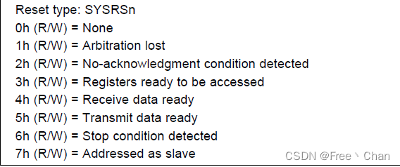
通过读寄存器值获取中断源状态:
    Uint16 IntSource;
	// Read interrupt source
    IntSource = I2caRegs.I2CISRC.all;
对应程序定义:
// Interrupt Source Messages
#define I2C_NO_ISRC             0x0000
#define I2C_ARB_ISRC            0x0001
#define I2C_NACK_ISRC           0x0002
#define I2C_ARDY_ISRC           0x0003
#define I2C_RX_ISRC             0x0004
#define I2C_TX_ISRC             0x0005
#define I2C_SCD_ISRC            0x0006
#define I2C_AAS_ISRC            0x0007
2.13 I2CEMDR
略
2.14 I2CPSC
I2C预分配寄存器
2.15 I2CFFTX
I2C发送FIFO寄存器
2.16 I2CFFRX
I2C接收FIFO寄存器
三、代码说明
以官方例程:Example_2833xI2C_eeprom.c为例。
I2C消息结构体:
| 变量名 | 含义 |
|---|---|
| MsgStatus | I2C状态 |
| SlaveAddress | 从机地址 |
| NumOfBytes | 写入字节数 |
| MemoryHighAddr | 内存写入的高位地址 |
| MemoryLowAddr | 内存写入的低位地址 |
| MsgBuffer[I2C_MAX_BUFFER_SIZE] | 消息写入队列 |
//
// I2C Message Structure
//
struct I2CMSG
{
    Uint16 MsgStatus;	// Word stating what state msg is in:
                        //   I2C_MSGCMD_INACTIVE = do not send msg
                        //   I2C_MSGCMD_BUSY = msg start has been sent,
                        //                     awaiting stop
                        //   I2C_MSGCMD_SEND_WITHSTOP = command to send
                        //       master trans msg complete with a stop bit
                        //   I2C_MSGCMD_SEND_NOSTOP = command to send
                        //       master trans msg without the stop bit
                        //   I2C_MSGCMD_RESTART = command to send a restart
                        //       as a master receiver with a stop bit
    Uint16 SlaveAddress; // I2C address of slave msg is intended for
    Uint16 NumOfBytes;	 // Num of valid bytes in (or to be put in MsgBuffer)

    //
    // EEPROM address of data associated with msg (high byte)
    //
    Uint16 MemoryHighAddr;

    //
    // EEPROM address of data associated with msg (low byte)
    //
    Uint16 MemoryLowAddr;

    //
    // Array holding msg data - max that MAX_BUFFER_SIZE can be is 16 due to
    // the FIFO's
    Uint16 MsgBuffer[I2C_MAX_BUFFER_SIZE];
};
I2CA初始化函数:
–将main函数部分初始化定义项也复制到I2CA_Init(void)中
–一般修改I2caRegs.I2CCLKL和I2caRegs.I2CCLKH的值(公式见1.1)
void I2CA_Init(void)
{
   // 初始化I2C GPIO功能
   InitI2CGpio();
   // 初始化I2C
   I2caRegs.I2CSAR = 0x0050;		// EEPROM的从机地址
   // I2C模块频率 = 10MHz
   #if (CPU_FRQ_150MHZ)
        I2caRegs.I2CPSC.all = 14;
   #endif
   #if (CPU_FRQ_100MHZ)
     I2caRegs.I2CPSC.all = 9;
   #endif
   //Master Clock(SCL) = 10MHz / (10 + 5) + (5 + 5) = 400KHz
   I2caRegs.I2CCLKL = 10;			// NOTE: 这两个赋值必须不能等于0
   I2caRegs.I2CCLKH = 5;
   //SCD: 停止条件产生中断,ARDY: 寄存器访问就绪产生中断
   I2caRegs.I2CIER.all = 0x24;

   I2caRegs.I2CMDR.all = 0x0020;	// 使能I2C(释放总线的效果)

   I2caRegs.I2CFFTX.all = 0x6000;	// 使能FIFO模式和发送FIFO
   I2caRegs.I2CFFRX.all = 0x2040;	// 使能接收FIFO, 清除RXFFINT标志位,

   //中断服务函数入口
   EALLOW;
   PieVectTable.I2CINT1A = &i2c_int1a_isr;
   EDIS;

	// Enable I2C interrupt 1 in the PIE: Group 8 interrupt 1
   PieCtrlRegs.PIEIER8.bit.INTx1 = 1;

   // Enable CPU INT8 which is connected to PIE group 8
   IER |= M_INT8;
   return;
}
I2CA写数据和读数据函数:
Uint16 I2CA_WriteData(struct I2CMSG *msg)
{
   Uint16 i;
   // STP位在发送完数据后会清零
   if (I2caRegs.I2CMDR.bit.STP == 1)
      return I2C_STP_NOT_READY_ERROR;

   // 设置从机地址
   I2caRegs.I2CSAR = msg->SlaveAddress;
   // 检查总线是否忙
   if (I2caRegs.I2CSTR.bit.BB == 1)
      return I2C_BUS_BUSY_ERROR;
   // 设置发送字节:发送的数目+2位地址
   I2caRegs.I2CCNT = msg->NumOfBytes+2;
   // 发送16位地址
   I2caRegs.I2CDXR = msg->MemoryHighAddr;
   I2caRegs.I2CDXR = msg->MemoryLowAddr;
   for (i=0; i<msg->NumOfBytes; i++)
   {
      I2caRegs.I2CDXR = *(msg->MsgBuffer+i);
   }
   // 作为主机开始发送
   // FREE、STT、STP、MST、TRX、IRS
   I2caRegs.I2CMDR.all = 0x6E20;

   return I2C_SUCCESS;
}


Uint16 I2CA_ReadData(struct I2CMSG *msg)
{
   // 检查STP
   if (I2caRegs.I2CMDR.bit.STP == 1)
      return I2C_STP_NOT_READY_ERROR;
   // 发送从机地址
   I2caRegs.I2CSAR = msg->SlaveAddress;
   // 发送读取地址
   if(msg->MsgStatus == I2C_MSGSTAT_SEND_NOSTOP)
   {
      // I2C模块已在总线上接收或传输START位时置1
      // 所以执行了发送控制字后,bus busy状态=1,后面else if就没有判断BB状态
      if (I2caRegs.I2CSTR.bit.BB == 1)
         return I2C_BUS_BUSY_ERROR;
      // 发送内存地址
      I2caRegs.I2CCNT = 2;
      I2caRegs.I2CDXR = msg->MemoryHighAddr;
      I2caRegs.I2CDXR = msg->MemoryLowAddr;
      I2caRegs.I2CMDR.all = 0x2620;  //这里比前面发送函数少了一个停止位
   }
   // dsp发送内存地址后,状态切换为:I2C_MSGSTAT_RESTART,开始接收数据
   else if(msg->MsgStatus == I2C_MSGSTAT_RESTART)
   {
      I2caRegs.I2CCNT = msg->NumOfBytes;	// 设置接收的字节数
      I2caRegs.I2CMDR.all = 0x2C20;			// TRX = 0:接收
   }
   return I2C_SUCCESS;
}
I2C读写函数(读和写整合在一起):
–该函数根据自己所需做修改
//=====================================================================
//
// 读写I2C数据
// mode:RW_I2C_WRITE or RW_I2C_READ
//=====================================================================
Uint16 RwI2cBus(Uint16 mode)
{
    int16 i;

    if (I2caRegs.I2CMDR.bit.STP == 1)
    {
        return I2C_STP_NOT_READY_ERROR;
    }

    if ((I2caRegs.I2CSTR.bit.BB == 1) && (I2cMsg.status != I2C_MSGSTAT_RESTART))
    {
        return I2C_BUS_BUSY_ERROR;
    }

    I2caRegs.I2CSAR = I2C_SLAVE_ADDR;

    if (mode == RW_I2C_WRITE)
    {
        // Setup number of bytes to send
        // buffer + Address

        I2caRegs.I2CCNT = I2cMsg.NumOfBytes+ 2;
        I2caRegs.I2CDXR = I2cMsg.MemoryHighAddr; // Setup data to send
        I2caRegs.I2CDXR = I2cMsg.MemoryLowAddr;

        for (i = 0; i < I2cMsg.bytes; i++)
        {
            I2caRegs.I2CDXR = I2cMsg.MsgBuffer[i];
        }

        // Send start as master transmitter
        I2caRegs.I2CMDR.all = 0x6E20;   // S.A.D.P
    }
    else if ((mode == RW_I2C_READ) && (I2C_MSGSTAT_RESTART == I2cMsg.status))
    {
        I2caRegs.I2CCNT = I2cMsg.NumOfBytes; // Setup how many bytes to expect
        I2caRegs.I2CMDR.all = 0x2C20;   // Send restart as master receiver
                                        // S.A.D.P
    }
    else                                // ACK, or start read
    {
        I2caRegs.I2CCNT = 2;
        I2caRegs.I2CDXR = I2cMsg.MemoryHighAddr;
        I2caRegs.I2CDXR = I2cMsg.MemoryLowAddr;

        I2caRegs.I2CMDR.all = 0x2620;   // Send data to setup EEPROM address
                                        // S.A.D
    }

    return I2C_SUCCESS;
}
I2CA中断服务函数:
–删除了例程中对比读数据和写数据的操作
__interrupt void i2c_int1a_isr(void)     // I2C-A
{
   Uint16 IntSource, i;

   // 读取中断源
   IntSource = I2caRegs.I2CISRC.all;
   if(IntSource == I2C_SCD_ISRC) // 中断源:停止条件产生
   {
      // 如果是在写,将状态清为空闲
      // 开始写的时候,设置状态位为I2C_MSGSTAT_WRITE_BUSY,若产生停止位,代表写结束
      if (CurrentMsgPtr->MsgStatus == I2C_MSGSTAT_WRITE_BUSY)
      {
         CurrentMsgPtr->MsgStatus = I2C_MSGSTAT_INACTIVE;
      }
      else
      {
         // 如果状态是NOSTOP_BUSY,还进入了停止位中断源,重置状态为NOSTOP重新发送
         if(CurrentMsgPtr->MsgStatus == I2C_MSGSTAT_SEND_NOSTOP_BUSY)
         {
            CurrentMsgPtr->MsgStatus = I2C_MSGSTAT_SEND_NOSTOP;
         }
         // 完成读数据,设置状态为空闲并读取参数
         else if (CurrentMsgPtr->MsgStatus == I2C_MSGSTAT_READ_BUSY)
         {
            CurrentMsgPtr->MsgStatus = I2C_MSGSTAT_INACTIVE;
            for(i=0; i < I2C_NUMBYTES; i++)
            {
              CurrentMsgPtr->MsgBuffer[i] = I2caRegs.I2CDRR;
            }
		 }
      }
   }
   else if(IntSource == I2C_ARDY_ISRC) // 中断源:寄存器访问就绪
   {
      if(I2caRegs.I2CSTR.bit.NACK == 1) // 如果没响应
      {
         I2caRegs.I2CMDR.bit.STP = 1;  //发送停止位
         I2caRegs.I2CSTR.all = I2C_CLR_NACK_BIT; //无应答位清零
      }
      // 如果发送了NOSTOP,重置状态为RESTART
      else if(CurrentMsgPtr->MsgStatus == I2C_MSGSTAT_SEND_NOSTOP_BUSY)
      {
         CurrentMsgPtr->MsgStatus = I2C_MSGSTAT_RESTART; //重新开始
      }
   }
   else // 只设置了SCD、ARDY中断源
   {	// 无效中断源
      __asm("   ESTOP0");
   }
   PieCtrlRegs.PIEACK.all = PIEACK_GROUP8;
}
main函数 loop:
–通过例程的main函数可以发现:
–信息队列msg的状态位比较重要,它可以查看写和读队列的当前状态,通过该位状态来执行下一步操作。
   // Application loop
   for(;;)
   {
      //
      // Write data to EEPROM section //
      //

      // 该例程将I2cMsgOut1的状态位设置成I2C_MSGSTAT_SEND_WITHSTOP
      // 所以作一个判断进入,进行写操作
      if(I2cMsgOut1.MsgStatus == I2C_MSGSTAT_SEND_WITHSTOP)
      {
         Error = I2CA_WriteData(&I2cMsgOut1);
         //写成功后将CurrentMsgPtr指向I2cMsgOut1,在中断服务函数中进行状态变更
         //将I2cMsgOut1状态设置成I2C_MSGSTAT_WRITE_BUSY
         if (Error == I2C_SUCCESS)
         {
            CurrentMsgPtr = &I2cMsgOut1;
            I2cMsgOut1.MsgStatus = I2C_MSGSTAT_WRITE_BUSY;
         }
      }  // end of write section

      ///
      // Read data from EEPROM section //
      ///

	  // 当写入完成后,I2cMsgOut1状态设置成I2C_MSGSTAT_INACTIVE表示完成
      if (I2cMsgOut1.MsgStatus == I2C_MSGSTAT_INACTIVE)
      {
		 // 该例程将I2cMsgIn1的状态位初始化为I2C_MSGSTAT_SEND_WITHSTOP
		 // 所以作一个判断进入,然后进行读操作
         if(I2cMsgIn1.MsgStatus == I2C_MSGSTAT_SEND_NOSTOP)
         {
            // 发送控制节
            while(I2CA_ReadData(&I2cMsgIn1) != I2C_SUCCESS)
            {
            }
            // 更新指针和状态
            CurrentMsgPtr = &I2cMsgIn1;
            I2cMsgIn1.MsgStatus = I2C_MSGSTAT_SEND_NOSTOP_BUSY;
         }
         else if(I2cMsgIn1.MsgStatus == I2C_MSGSTAT_RESTART)
         {
            // 读取数据
            while(I2CA_ReadData(&I2cMsgIn1) != I2C_SUCCESS)
            {
            }
            // 更新指针和状态
            CurrentMsgPtr = &I2cMsgIn1;
            I2cMsgIn1.MsgStatus = I2C_MSGSTAT_READ_BUSY;
         }
      }  // end of read section

   }   // end of for(;;)
梳理状态过程
MsgStatus:
// I2C  Message Commands for I2CMSG struct
#define I2C_MSGSTAT_INACTIVE          0x0000	// 空闲
#define I2C_MSGSTAT_SEND_WITHSTOP     0x0010	// 发送带停止位
#define I2C_MSGSTAT_WRITE_BUSY        0x0011	// 写状态忙
#define I2C_MSGSTAT_SEND_NOSTOP       0x0020	// 发送不带停止
#define I2C_MSGSTAT_SEND_NOSTOP_BUSY  0x0021	// 发送状态忙
#define I2C_MSGSTAT_RESTART           0x0022	// 重新开始
#define I2C_MSGSTAT_READ_BUSY         0x0023	// 读状态忙
写数据状态切换: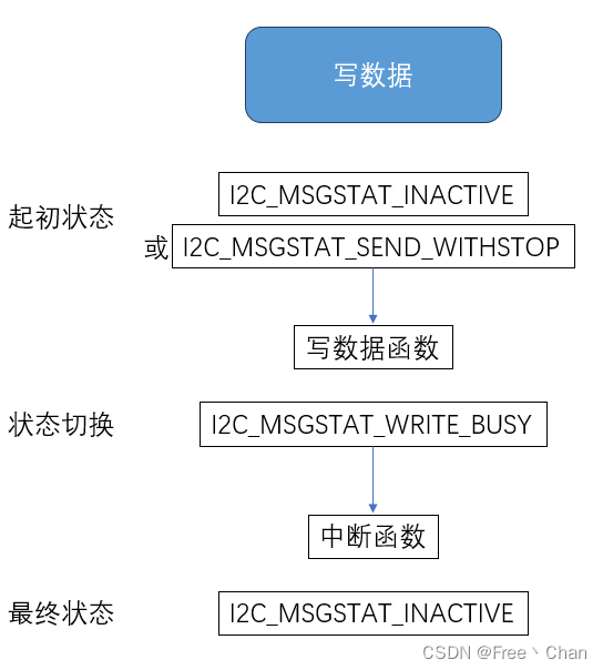
读数据状态:
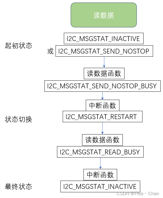
四、示例代码
I2C操作EEPROM代码:
i2c_eeprom.c
i2c_eeprom.h文章来源:https://www.toymoban.com/news/detail-821586.html
总结
本篇为DSP F28335 I2C配置的学习记录,结合官方例程进一步说明,完整代码去看官方例程。(个人学习记录分享,若侵权删)文章来源地址https://www.toymoban.com/news/detail-821586.html
到了这里,关于DSPF2833x:IIC配置[DSP I2C]的文章就介绍完了。如果您还想了解更多内容,请在右上角搜索TOY模板网以前的文章或继续浏览下面的相关文章,希望大家以后多多支持TOY模板网!


